Drive Positions
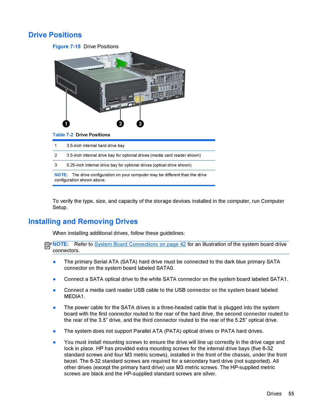
Figure 7-15 Drive Positions
Table 7-2 Drive Positions
1
2
3
NOTE: The drive configuration on your computer may be different than the drive configuration shown above.
To verify the type, size, and capacity of the storage devices installed in the computer, run Computer Setup.
Installing and Removing Drives
When installing additional drives, follow these guidelines:
![]()
![]()
![]()
![]() NOTE: Refer to System Board Connections on page 42 for an illustration of the system board drive connectors.
NOTE: Refer to System Board Connections on page 42 for an illustration of the system board drive connectors.
●The primary Serial ATA (SATA) hard drive must be connected to the dark blue primary SATA connector on the system board labeled SATA0.
●Connect a SATA optical drive to the white SATA connector on the system board labeled SATA1.
●Connect a media card reader USB cable to the USB connector on the system board labeled MEDIA1.
●The power cable for the SATA drives is a
●The system does not support Parallel ATA (PATA) optical drives or PATA hard drives.
●You must install mounting screws to ensure the drive will line up correctly in the drive cage and lock in place. HP has provided extra mounting screws for the internal drive bays (five
Drives 55