Manuals
/
HP
/
Computer Equipment
/
Personal Computer
HP
D8C84UT#ABA, D3K21UT#ABA Illustrated parts catalog, Spare parts, Computer major components
Models:
D8C84UT#ABA
D3K21UT#ABA
D3K19UT D3K19UT#ABA
Pro 4300 C9H69UT#ABA
Pro 4300 B8T87UT B8T87UT#ABA
Pro 4300 B5P90UT#ABA
Pro 4300 C9H67UT#ABA
1
35
160
160
Download
160 pages
41.85 Kb
32
33
34
35
36
37
38
39
Specifications
Install
Error codes
Password
Maintenance
Solving General Problems
Accessing Disk Image ISO Files
Computer Setup F10 Utility
Cables and Connectors
Preparation for Disassembly
Page 35
Image 35
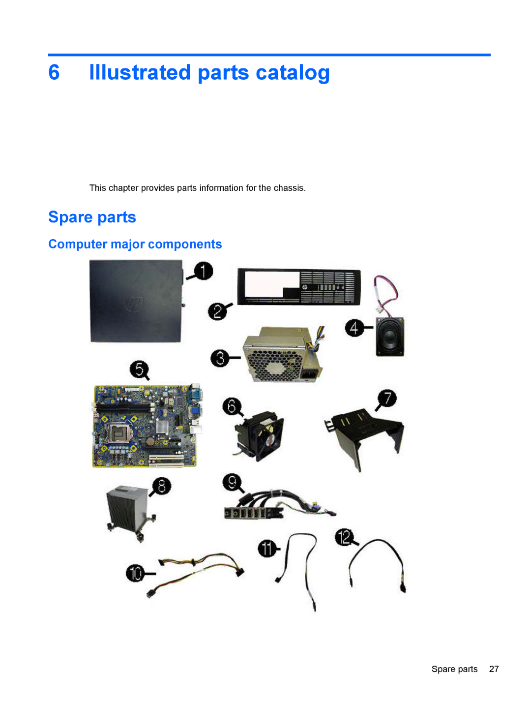
6 Illustrated parts catalog
This chapter provides parts information for the chassis.
Spare parts
Computer major components
Spare parts 27
Page 34
Page 36
Page 35
Image 35
Page 34
Page 36
Contents
Maintenance and Service Guide
HP Compaq Pro 4300 Small Form Factor Business PC
Iii
About This Book
Iv About This Book
Table of contents
Illustrated parts catalog
Safety and Comfort Vii
108
Choosing recovery media 146 Creating recovery media
103
105
Standard Configuration Features
Product Features
1Front Panel Components
Product Features
Front Panel Components
2Rear Panel Components
Rear Panel Components
Serial Number Location
4Serial Number and Product ID Location Product Features
Downloading Microsoft Windows Updates
Installing and Customizing the Software
Installing the Windows Operating System
Launching Windows XP from Windows
Installing or Upgrading Device Drivers Windows systems
Customizing the Monitor Display Windows systems
Accessing Disk Image ISO Files
Computer Setup F10 Utilities
Computer Setup F10 Utility
Using Computer Setup F10 Utilities
1Computer Setup-File
Computer Setup-File
Computer Setup F10 Utility
2Computer Setup-Storage
Computer Setup-Storage
3Computer Setup-Security
Computer Setup-Security
System Security
System IDs
Management
Computer Setup-Power
4Computer Setup-Power
Option Description Hardware Power
Bios Power-On
Computer Setup-Advanced
5Computer Setup-Advanced
Option Heading Power-On Options
Device Options
Bus Options
Sata Hard Drive Cables
Serial ATA Sata Drive Guidelines and Features
Serial ATA Hard Drive Characteristics
Sata Hard Drives
Hard Drive Capacities
Serial ATA Sata Drive Guidelines and Features
Smart ATA Drives
Small Form Factor SFF
Chassis Designations
Relative Humidity Event 55% 40% 10%
Electrostatic Discharge Information
Generating Static
Preventing Electrostatic Damage to Equipment
Static Shielding Protection Levels
Personal Grounding Methods and Equipment
Grounding the Work Area
Recommended Materials and Equipment
Operating Guidelines
Routine Care
General Cleaning Safety Precautions
Cleaning the Computer Case
Cleaning the Keyboard
Power Supply Fan
Service Considerations
Cleaning the Monitor
Cleaning the Mouse
Hard Drives
Cables and Connectors
Tools and Software Requirements
Screws
Lithium Coin Cell Battery
This chapter provides parts information for the chassis
Illustrated parts catalog
Spare parts
Computer major components
Illustrated parts catalog
Keyboard
Description Spare part number Optical drives
Expansion cards
Sequential part number listing
Spare parts
Illustrated parts catalog
Spare parts
Illustrated parts catalog
Spare parts
Illustrated parts catalog
1Serial Number and Product ID Location
Preparation for Disassembly
Page
Description Spare part number Access panel 636924-001
Computer Access Panel
Description Spare part number Front bezel 695080-001
Front Bezel
4Removing a Bezel Blank Replace the front bezel Bezel Blanks
Bezel Blanks
1System Board Connections
System Board Connector System Board Label Color Component
System Board Connections
DDR3-SDRAM DIMMs
Installing Additional Memory
DIMMs
Populating Dimm Sockets
Installing DIMMs
Page
Removing or Installing an Expansion Card
Remove the access panel Computer Access Panel on
Page
Page
Page
Page
Page
Cable Management
Drive cables
Drives
2Drive Positions
Installing and Removing Drives
Drive Positions
Mounting Screw Device
3Extra Mounting Screws
Removing an Internal 5.25-inch Drive
Rotate the drive cage back down to its normal position
Installing an Optical Drive into the 5.25-inch Drive Bay
Page
Removing an Internal 3.5-inch Drive
Page
Installing a Drive into the 3.5-inch Internal Drive Bay
Page
Page
Remove the access panel Computer Access Panel on
39Installing Hard Drive Mounting Screws Drives
Page
Description Spare part number Baffle 636921-001
Baffle
Description Spare part number Front fan assembly 636922-001
Front Fan Assembly
Remove the front bezel Front Bezel on
Front I/O, Power Switch Assembly
Description Spare part number Speaker 636925-001
Speaker
Description Spare part number Heat sink 636919-001
Heat sink
Page
Page
Processor
Page
Pwrcmd
Power Supply
Power supply connector label System board connector
4Power supply cable system board connector
System Board
Page
Battery
Lift the battery out of its holder
Type 1 Battery Holder
Type 2 Battery Holder
Type 3 Battery Holder
Using the Small Form Factor Computer in a Tower Orientation
HP/Kensington MicroSaver Security Cable Lock
Installing a Security Lock
Padlock
57Installing a Padlock Installing a Security Lock
Front Bezel Security
Page
General Requirements
Power Cord Set Requirements
Japanese Power Cord Requirements
Country Accrediting Agency
Country-Specific Requirements
Post Error Messages
Control panel message Description Recommended action
Post Numeric Codes and Text Messages
Post Numeric Codes and Text Messages
Table B-1Numeric Codes and Text Messages
Activity Blinks Possible Cause
Table B-2Diagnostic Front Panel LEDs and Audible Codes
Activity Blinks Possible Cause Recommended Action
Safety and Comfort Before You Call for Technical Support
Troubleshooting Without Diagnostics
Helpful Hints
Page
Computer date and time display is incorrect Cause Solution
Solving General Problems
Solving General Problems
Table C-1Solving General Problems
Poor performance is experienced Cause Solution
There is no sound or sound volume is too low Cause Solution
Cannot remove computer cover or access panel Cause
Cause Solution
Run Windows XP, Start Accessories Run
Appendix C Troubleshooting Without Diagnostics
Power supply shuts down intermittently Cause Solution
Solving Power Problems
Solving Power Problems
Table C-2Solving Power Problems
Usdt power supply adapter must be at 135W and use
Table C-3Solving Hard Drive Problems
Solving Hard Drive Problems
Solving Hard Drive Problems
Storage Boot Order
Nonsystem disk/NTLDR missing message Cause Solution
Computer will not boot from hard drive Cause Solution
Removable hard drive is not recognized by the computer Cause
Computer seems to be locked up Cause
Can not write to the media card Cause
Solving Media Card Reader Problems
Table C-4Solving Media Card Reader Problems
Solving Media Card Reader Problems
Personalization, select Adjust screen
Solving Display Problems
Table C-5Solving Display Problems
Blank screen no video Cause Solution
Solving Display Problems
Select ImageControl/ Horizontal Position or Vertical
Dim characters Cause Solution
Image is not centered Cause Solution
No Connection, Check Signal Cable displays on screen Cause
Clicking noise coming from inside a CRT monitor Cause
Out of Range displays on screen Cause
Symbol. Click Start All Programs Accessories
Certain typed symbols do not appear correct Cause Solution
Table C-6Solving Audio Problems
Solving Audio Problems
Solving Audio Problems
Line-in jack is not functioning properly Cause
Sound from headphones is not clear or muffled Cause
Advanced Device Options Internal Speaker
Table C-7Solving Printer Problems
Solving Printer Problems
Solving Printer Problems
Printer is offline Cause Solution
Printer prints garbled information Cause Solution
Table C-9Solving Mouse Problems
Solving Keyboard and Mouse Problems
Solving Keyboard and Mouse Problems
Table C-8Solving Keyboard Problems
Appendix C Troubleshooting Without Diagnostics
Computer will not start Cause Solution
Solving Hardware Installation Problems
Solving Hardware Installation Problems
Table C-10Solving Hardware Installation Problems
Appendix C Troubleshooting Without Diagnostics
Table C-11Solving Network Problems
Solving Network Problems
Solving Network Problems
Diagnostics reports a failure Cause Solution
Network status link light never flashes Cause Solution
New network card will not boot Cause Solution
Memory count during Post is wrong Cause Solution
Solving Memory Problems
Table C-12Solving Memory Problems
Out of memory error Cause Solution
Insufficient memory error during operation Cause Solution
Solving Memory Problems
Make sure the processor heat sink is installed properly
Solving Processor Problems
Table C-13Solving Processor Problems
Some fans only operate when needed
Mode in Security Password Options
Solving CD-ROM and DVD Problems
Solving CD-ROM and DVD Problems
Table C-14Solving CD-ROM and DVD Problems
Cannot eject compact disc tray-load unit Cause
Movie will not play in the DVD drive Cause Solution
Table C-15Solving USB Flash Drive Problems
Solving USB Flash Drive Problems
Solving USB Flash Drive Problems
Table C-16Solving Front Panel Component Problems
Solving Front Panel Component Problems
Table C-17Solving Internet Access Problems
Solving Internet Access Problems
Solving Internet Access Problems
Cannot automatically launch Internet programs Cause
Modem
Click on System and Maintenance
Double-clickAgere Systems PCI-SV92PP Soft
Table C-18Solving Software Problems
Solving Software Problems
Cmos
Password Security and Resetting
Resetting the Password Jumper
Figure D-1 Cmos button
Clearing and Resetting the Cmos
Page
Drive Protection System DPS
Select Storage DPS Self-Test
Accessing DPS Through Computer Setup
System Recovery
Appendix F System Recovery
System Recovery options
System Recovery from the Windows 7 Start Menu
System Recovery at system startup
System Recovery from recovery media
To create recovery discs Close all open programs
Recovery media
Choosing recovery media
Creating recovery media
Page
Table G-1Specifications
Specifications
Appendix G Specifications
149
Cmos
Index
DVI-D VGA
Sata
Connectors on system board
Top
Page
Image
Contents