6.Rotate the drive cage to its upright position (1) and install an M3 mounting screw in the back left side of the drive (2) to secure the drive to the drive cage.
Figure 7-23 Securing the Drive in the Drive Cage
7.Connect the SATA data cable to the white system board connector labeled SATA1 if it is not already connected.
8.Route the data cable through the cable guides.
CAUTION: There are two cable guides that keep the data cable from being pinched by the drive cage when raising or lowering it. One is located on the bottom side of the drive cage. The other is located on the chassis frame under the drive cage. Ensure that the data cable is routed through these guides before connecting it to the optical drive.
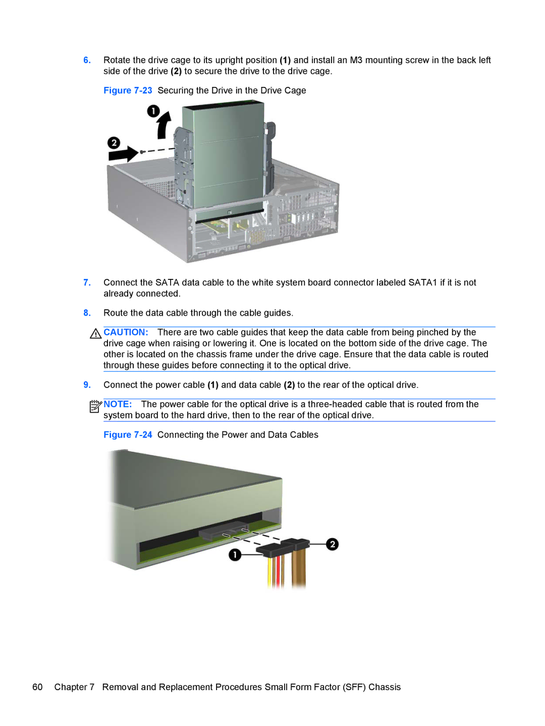
9.Connect the power cable (1) and data cable (2) to the rear of the optical drive.
![]()
![]()
![]()
![]() NOTE: The power cable for the optical drive is a
NOTE: The power cable for the optical drive is a