HPMA User Guide
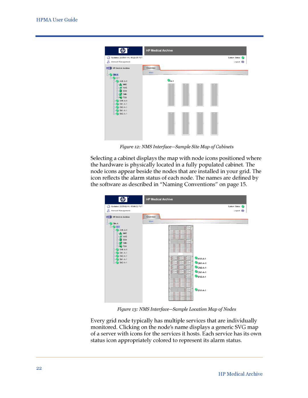
Figure 12: NMS Interface—Sample Site Map of Cabinets
Selecting a cabinet displays the map with node icons positioned where the hardware is physically located in a fully populated cabinet. The node icons appear beside the nodes that are installed in your grid. The icon reflects the alarm status of each node. The names are defined by the software as described in “Naming Conventions” on page 15.
Figure 13: NMS Interface—Sample Location Map of Nodes
Every grid node typically has multiple services that are individually monitored. Clicking on the node’s name displays a generic SVG map of a server with icons for the services it hosts. Each service has its own status icon appropriately colored to represent its alarm status.
22
HP Medical Archive