Expansion card slot identification
![]() NOTE: Read Warnings and cautions on page 59 before servicing this component.
NOTE: Read Warnings and cautions on page 59 before servicing this component.
This section identifies and describes workstation expansion card slots, and presents card configuration information.
Slot identification and description
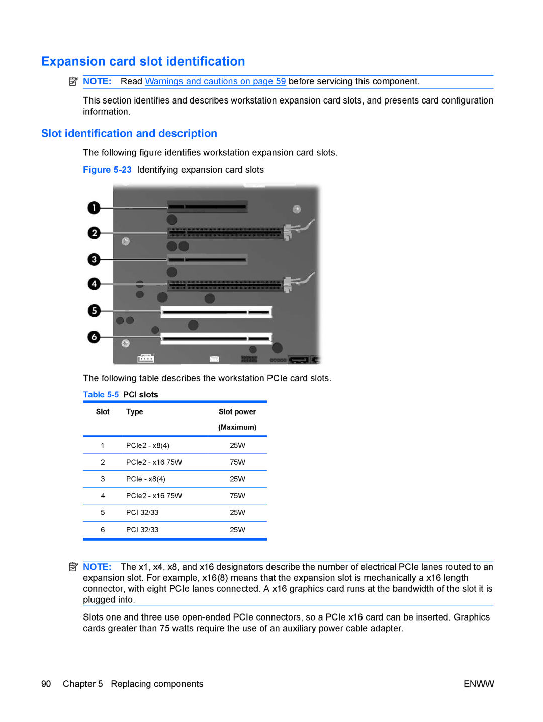
The following figure identifies workstation expansion card slots.
Figure 5-23 Identifying expansion card slots
The following table describes the workstation PCIe card slots.
Table
Slot | Type | Slot power |
|
| (Maximum) |
|
|
|
1 | PCIe2 - x8(4) | 25W |
|
|
|
2 | PCIe2 - x16 75W | 75W |
|
|
|
3 | PCIe - x8(4) | 25W |
|
|
|
4 | PCIe2 - x16 75W | 75W |
|
|
|
5 | PCI 32/33 | 25W |
|
|
|
6 | PCI 32/33 | 25W |
|
|
|
![]() NOTE: The x1, x4, x8, and x16 designators describe the number of electrical PCIe lanes routed to an expansion slot. For example, x16(8) means that the expansion slot is mechanically a x16 length connector, with eight PCIe lanes connected. A x16 graphics card runs at the bandwidth of the slot it is plugged into.
NOTE: The x1, x4, x8, and x16 designators describe the number of electrical PCIe lanes routed to an expansion slot. For example, x16(8) means that the expansion slot is mechanically a x16 length connector, with eight PCIe lanes connected. A x16 graphics card runs at the bandwidth of the slot it is plugged into.
Slots one and three use
90 Chapter 5 Replacing components | ENWW |