Removing and installing components
Component locations
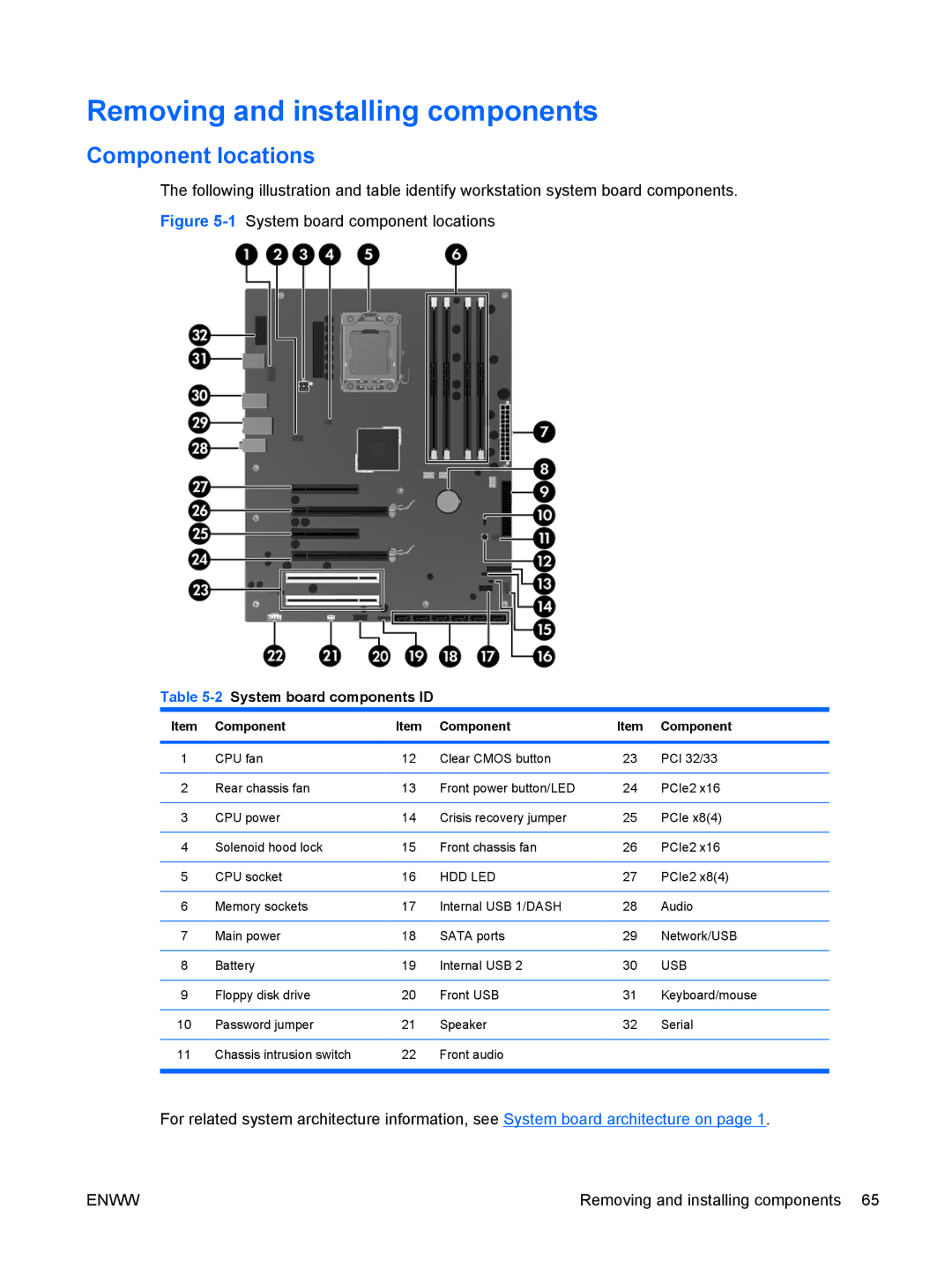
The following illustration and table identify workstation system board components.
Figure 5-1 System board component locations
Table 5-2 System board components ID
Item | Component | Item | Component | Item | Component |
|
|
|
|
|
|
1 | CPU fan | 12 | Clear CMOS button | 23 | PCI 32/33 |
|
|
|
|
|
|
2 | Rear chassis fan | 13 | Front power button/LED | 24 | PCIe2 x16 |
|
|
|
|
|
|
3 | CPU power | 14 | Crisis recovery jumper | 25 | PCIe x8(4) |
|
|
|
|
|
|
4 | Solenoid hood lock | 15 | Front chassis fan | 26 | PCIe2 x16 |
|
|
|
|
|
|
5 | CPU socket | 16 | HDD LED | 27 | PCIe2 x8(4) |
|
|
|
|
|
|
6 | Memory sockets | 17 | Internal USB 1/DASH | 28 | Audio |
|
|
|
|
|
|
7 | Main power | 18 | SATA ports | 29 | Network/USB |
|
|
|
|
|
|
8 | Battery | 19 | Internal USB 2 | 30 | USB |
|
|
|
|
|
|
9 | Floppy disk drive | 20 | Front USB | 31 | Keyboard/mouse |
|
|
|
|
|
|
10 | Password jumper | 21 | Speaker | 32 | Serial |
|
|
|
|
|
|
11 | Chassis intrusion switch | 22 | Front audio |
|
|
|
|
|
|
|
|
For related system architecture information, see System board architecture on page 1.
ENWW | Removing and installing components 65 |