Front panel components
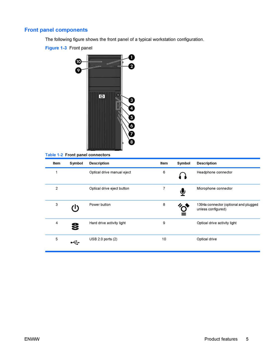
The following figure shows the front panel of a typical workstation configuration.
Figure 1-3 Front panel
Table 1-2 Front panel connectors
Item | Symbol | Description | Item | Symbol | Description |
|
|
|
|
|
|
1 |
| Optical drive manual eject | 6 |
| Headphone connector |
|
|
|
|
|
|
2 |
| Optical drive eject button | 7 |
| Microphone connector |
|
|
|
|
|
|
3 |
| Power button | 8 |
| 1394a connector (optional and plugged |
|
|
|
|
| unless configured) |
|
|
|
|
|
|
4 |
| Hard drive activity light | 9 |
| Optical drive activity light |
|
|
|
|
|
|
5 |
| USB 2.0 ports (2) | 10 |
| Optical drive |
|
|
|
|
|
|
ENWW | Product features 5 |