3.Tighten the top cover screws.
4.Set the key mode switch back to its normal position.
5.If your system unit has a rear cover, do the replacement procedure in ªRear Coverº on page
6.Connect the power cable.
7.Set the power switches of the attached devices to On.
8.Set the power switch of the system unit to On.
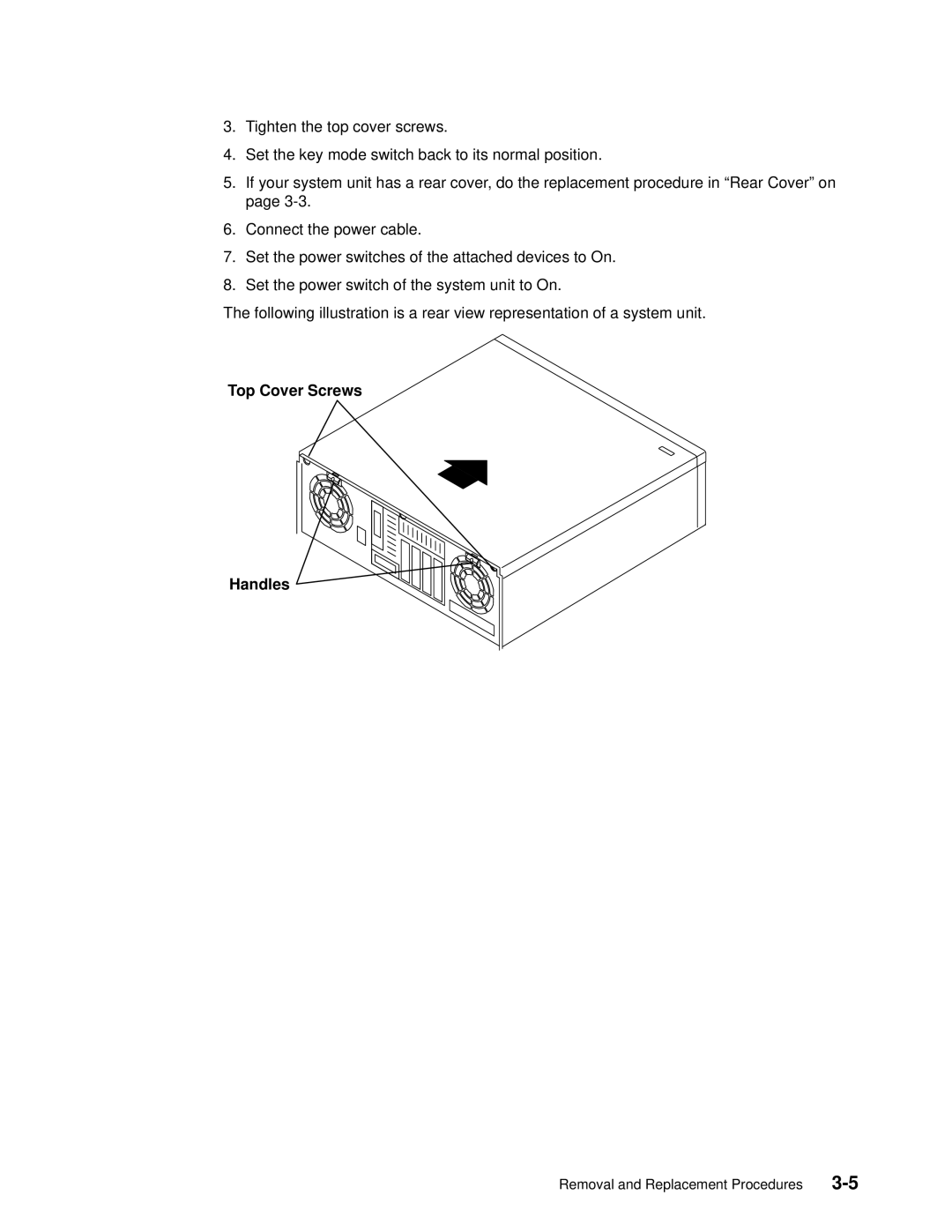
The following illustration is a rear view representation of a system unit.
Top Cover Screws
Handles
Removal and Replacement Procedures |