Main
First Edition (October 1997)
7012 Models 300 Series Installation and Service Guide.
R/S6000
Table of Contents
iv
Communications Statements
Federal Communications Commission (FCC) Statement
European Union (EU) Statement
International Electrotechnical Commission (IEC) Statement
vi
United Kingdom Telecommunications Safety Requirements
Avis de conformit aux normes du ministre des Communications du Canada
Canadian Department of Communications Compliance Statement
VCCI Statement
Electromagnetic Interference (EMI) Statement Taiwan
Radio Protection for Germany
Page
Safety Notices
Definitions of Safety Notices
x
Laser Safety Information
About This Book
Related Information
Chapter 1. Reference Information
System Unit Locations
Front View with Covers, Early Models
1-2
Front View with Covers, Later Models
Rear View without Covers, Models 320, 32E, 32H
Rear View without Covers, Models 340, 34H, 350, 355, 360/36T, 365, 370/37T, 375
Rear View Models 380, 390, 39H, and 397
1-4
Front View without Covers, Early Models
Front View without Covers Later Models
Front View without Covers Model 397
System Planar Connector Locations, Models 320, 32E, 32H
1-6
System Planar Connector Locations, Models 355, 365, 375
System Planar Connector Locations, Models 340, 34H, 350, 360/36T, 370/37T
System Planar Connector Locations Models 380 and 390
System Planar Connector Locations Model 39H
1-8
System Planar Connector Locations Model 397
CPU Card Locations
Memory
Model 39H
Model 397
1-10
Data and Power Flow
Bus-Attached Disk Drives, Models 320, 32E, and 32H
SCSI-Attached Disk Drives, Models 340, 34H, 350, 360/36T, 370/37T
SCSI-Attached Disk Drives, Models 355, 365, 375
1-12
Data and Power Flow: SCSI Attached Disk Drives Models 380, 390, 39H
Data and Power Flow: SCSI Attached Disk Drives Model 397
1-14
Specifications (all models except 380, 390, 39H, and 397)
Specifications Models 380, 390, 39H, and 397
1-16
Power Cables
Service Inspection Guide
1-18
Page
2-1520-1
Chapter 2. Maintenance Analysis Procedures (MAPS)
MAP 1520: 7012 Power MAP
2-1520-2
Step 1
Step 2
Step 3
2-1520-3
Step 4
2-1520-4
Step 5
Step 6
Step 7
2-1520-5
Step 8
2-1520-6
Step 9
Step 10
2-1520-7
Step 11
Step 12
2-1520-8
Step 13
Step 14
Step 15
2-1520-9
Step 16
Step 17
2-1520-10
Step 18
Step 19
Step 20
2-1520-11
Step 21
Step 22
Step 23
2-1520-12
Step 24
Step 25
MAP 1540: 7012 Minimum Machine Configuration
POWERstation and POWERserver Common Diagnostics and Service Guide.
Diagnostic Information For Micro Channel Bus Systems
2-1540-2
Step 1
Step 2
2-1540-4
Step 3
Step 4
2-1540-6
Step 5
Step 6
2-1540-8
Step 7
Step 8
2-1540-10
Step 9
Page
2-1540-12
Step 10
POWERstation and POWERserver Common Diagnostics and Service Guide.
Step 11
2-1540-14
Step 12
Step 13
2-1540-16
Step 14
Step 15
Step 16
Chapter 3. Removal and Replacement Procedures
3-2
Handling Static-Sensitive Devices
Rear Cover
Removal
3-4
Top Cover
Page
3-6
Front Cover
Page
3-8
Disk Drive (Bus-Attached): Models 320, 32E, 32H
Page
3-10
Disk Drive (SCSI-Attached): Models 320, 32E, 32H
Page
3-12
Disk Drive (SCSI-Attached): Models 340, 34H, 350, 355, 360/36T, 365, 370/37T, 375
Page
3-14
Disk Drive: Models 380, 390, 39H, and 397
Removal
Page
3-16
Power Supply
Page
3-18
Power Supply (Models 380, 390, 39H, and 397)
Removal
Page
3-20
Diskette Drive
Page
3-22
Media Drive Removal for Models 380, 390, 39H, and 397
Removal
Page
3-24
Adapter Cards, Ethernet Riser Card, and External Diskette Riser Card
Removal
Page
3-26
Setting the Ethernet Riser Card Jumpers
Thick/Thin Ethernet Riser
Twisted-Pair Ethernet Riser
3-28
Attached Devices
Removal
3-30
CPU Card
CPU Card (Model 39H)
3-32
Voltage Regulator Card (Model 39H)
3-34
L2 Cache
Removal
Fan and Air Duct (Model 39H Only)
Removal
Page
Memory Card
3-38
Memory SIMMs
Removal
3-40
System Planar
Page
3-42
Card Guide Frame
3-44
Rear Fan
3-46
Front Fan
Page
3-48
Key Lock
Page
3-50
Reset Switch
Page
3-52
Serial Ports Flex Circuit (Models 340, 34H, 350, 355, 360/36T, 365, 370/37T, 375)
Serial Port (Models 380, 390, 39H, and 397)
3-54
Three-Digit Display: Models 320, 32E, 32H
Three-Digit Display Models 340, 34H, 350, 355, 360/36T, 365, 370/37T, and 375, 380, 390, 39H
3-56
Three-Digit Display, Model 397
Toroids
Removal
3-58
Battery
Removal
Contact Strips (Models 340, 34H, 350, 355, 360/36T, 365, 370/37T, 375)
Removal
Chapter 4. System Installation
Step 1. Inventory
4-2
Step 2. Observe this Safety Notice during Installation
Step 3. Checking Customer Outlets
4-4
Step 4. Setting Up the System Unit
not
Step 5. Set Up Each Device Being Attached
Step 6. Connecting Devices to Standard I/O Ports
Diagnostic Information For Micro Channel Bus Systems
4-6
Step 7. Connecting Devices to the Adapters
Step 8. Arranging the System Unit and Devices
Page
5-2
Covers and Electronics
Page
5-4
Covers and Electronics
Diagnostic Information For Micro Channel Bus Systems
5-6
Covers and Electronics (Models 380, 390, 39H, and 397)
Diagnostic Information For Micro Channel Bus Systems
5-8
Front Card Guide
Page
5-10
Front Card Guide (Models 380, 390, 39H, and 397)
Page
5-12
Drives and Power, Early Models
Diagnostic Information For Micro Channel Bus Systems
5-14
Drives and Power (Models 380, 390, 39H, and 397)
Page
5-16
Power Cables
Appendix A. SCSI Device Address Record
Internally Installed SCSI Device Record
Models 320, 32E, 32H
A-2
Models 340,34H 350, 355, 360/36T, 365, 370/37T, 375
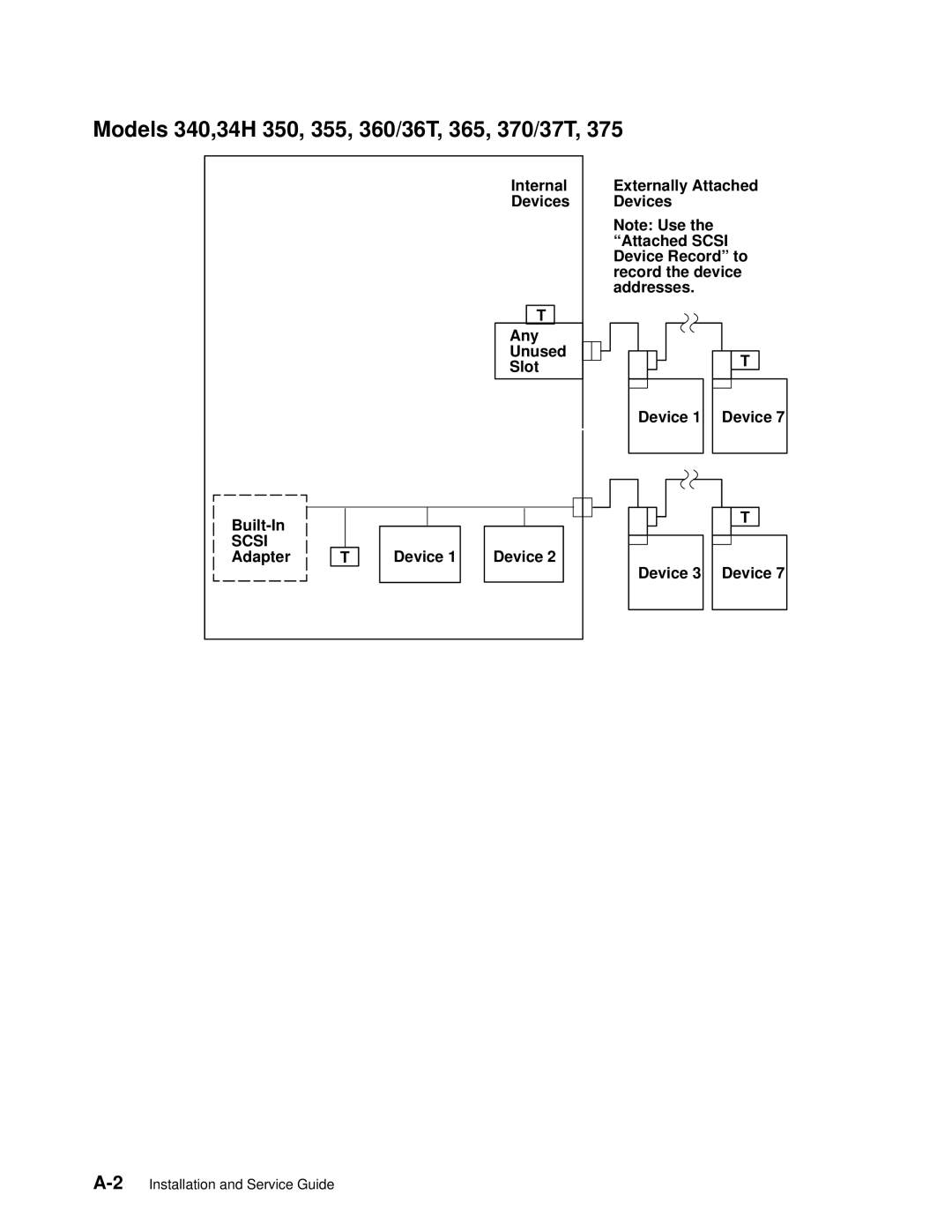
Models 380, 390, 39H, and 397
A-4
Page
A-6
Page
X-2
M
O
P
R
S