Serial Ports Flex Circuit (Models 340, 34H, 350, 355, 360/36T, 365, 370/37T, 375)
Removal
1.Set the power switches of the attached devices to Off.
2.Set the power switch of the system unit to Off.
3.Do the removal procedure in ªRear Coverº on page
4.Remove the power cable.
5.Do the removal procedure in ªTop Coverº on page
6.Do the removal procedure in ªFront Coverº on page
7.Do the removal procedure in ªDisk Drive
8.Do the removal procedure in ªPower Supplyº on page
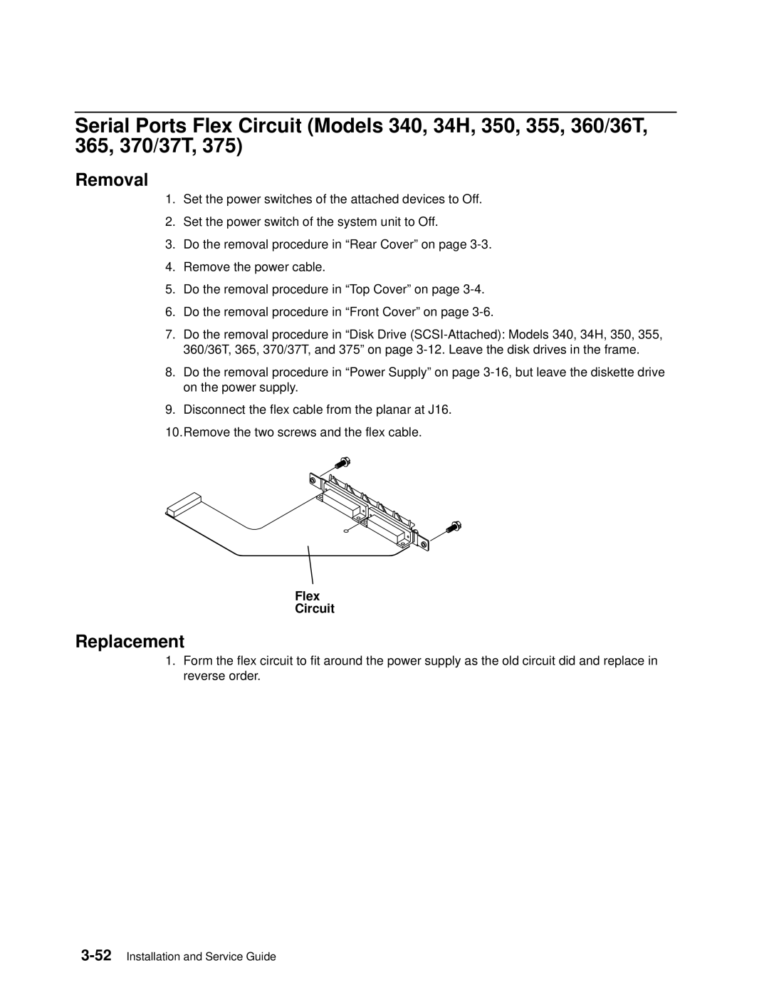
9.Disconnect the flex cable from the planar at J16.
10.Remove the two screws and the flex cable.
Flex
Circuit
Replacement
1.Form the flex circuit to fit around the power supply as the old circuit did and replace in reverse order.