Replacement
1.Be sure that the aligning tabs on the base are not bent.
2.Place the power supply approximately 5 mm
3.Push it to the rear to engage the tabs on the base with the slots on the power supply.
4.Tighten the power supply mounting screw.
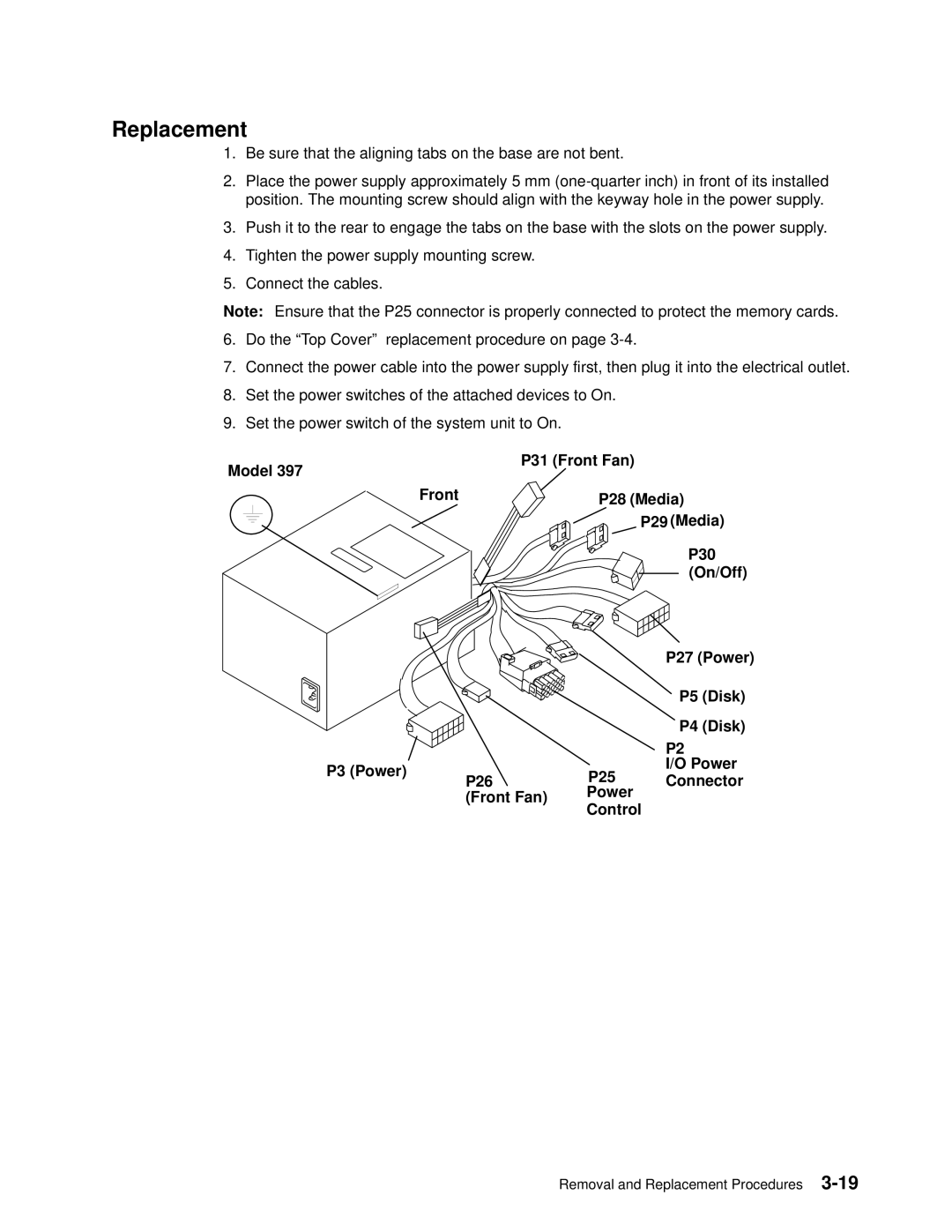
5.Connect the cables.
Note: Ensure that the P25 connector is properly connected to protect the memory cards.
6.Do the ªTop Coverº replacement procedure on page
7.Connect the power cable into the power supply first, then plug it into the electrical outlet.
8.Set the power switches of the attached devices to On.
9.Set the power switch of the system unit to On.
Model 397
P31 (Front Fan)
Front | P28 (Media) |
|
![]() P29 (Media)
P29 (Media)
P30
(On/Off)
|
| P27 (Power) | |
|
| P5 (Disk) | |
|
| P4 (Disk) | |
|
| P2 | |
P3 (Power) | P25 | I/O Power | |
Connector | |||
P26 | |||
(Front Fan) | Power |
| |
Control |
| ||
|
|
Removal and Replacement Procedures