Card Guide Frame
Removal
1.Set the power switches of the attached devices to Off.
2.Set the power switches of the system unit to Off.
3.Unplug the power cord from the electrical outlet.
4.If the system unit has a rear cover, do the Rear Cover removal procedure on page
5.Do the Top Cover removal procedure on page
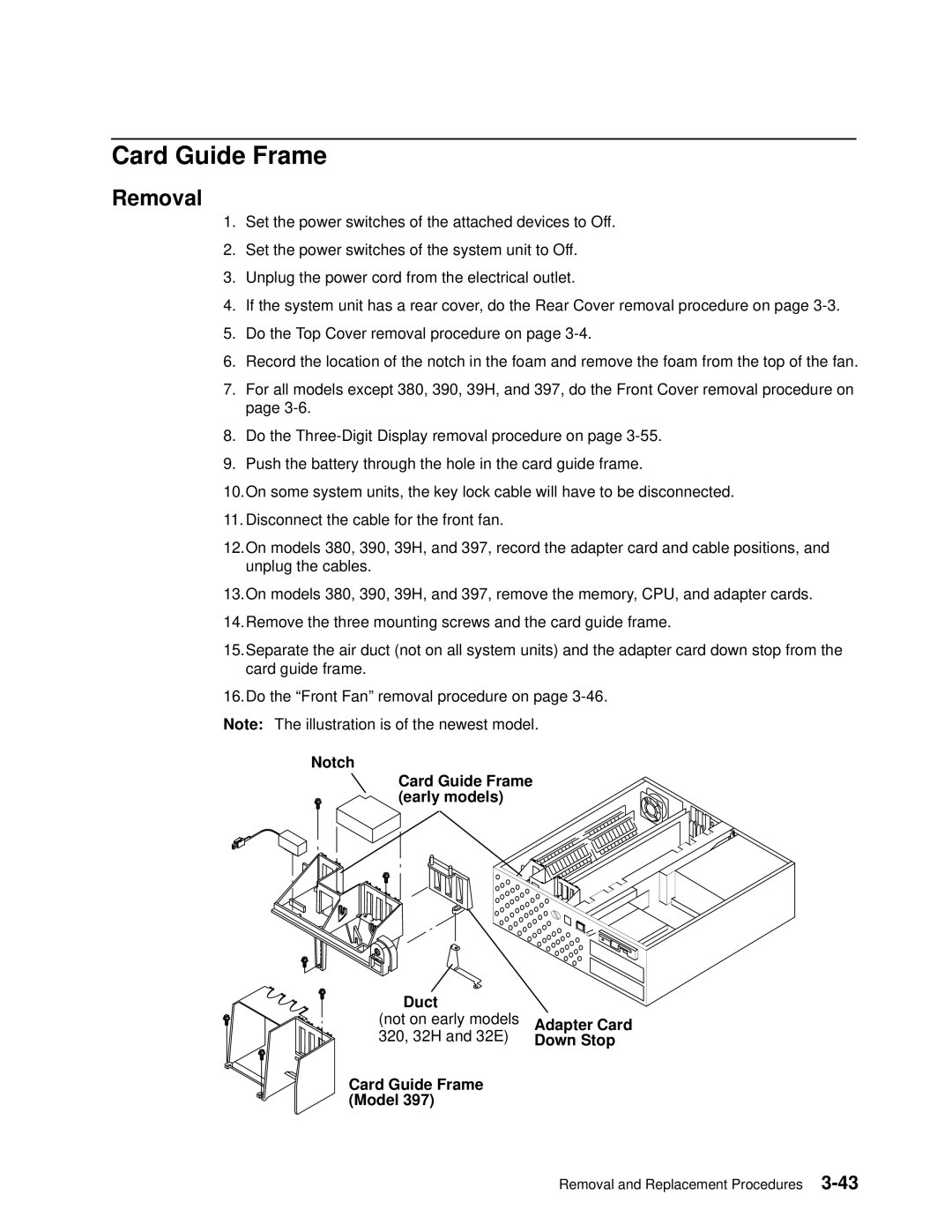
6.Record the location of the notch in the foam and remove the foam from the top of the fan.
7.For all models except 380, 390, 39H, and 397, do the Front Cover removal procedure on page
8.Do the
9.Push the battery through the hole in the card guide frame.
10.On some system units, the key lock cable will have to be disconnected.
11. Disconnect the cable for the front fan.
12.On models 380, 390, 39H, and 397, record the adapter card and cable positions, and unplug the cables.
13.On models 380, 390, 39H, and 397, remove the memory, CPU, and adapter cards. 14.Remove the three mounting screws and the card guide frame.
15.Separate the air duct (not on all system units) and the adapter card down stop from the card guide frame.
16.Do the ªFront Fanº removal procedure on page
Notch
Card Guide Frame (early models)
Duct |
|
(not on early models | Adapter Card |
320, 32H and 32E) | Down Stop |
Card Guide Frame |
|
(Model 397) |
|
Removal and Replacement Procedures