CPU Card
Note: Refer to ªHandling
Removal
1.Set the power switches of the attached devices to Off.
2.Set the power switch of the system unit to Off.
3.If the system unit has a rear cover, do the rear cover removal procedure on page
4.Do the Top Cover removal procedure on page
5.On Models 340 and 350, remove the CPU shield.
6.Make a note of its position and remove the CPU card.
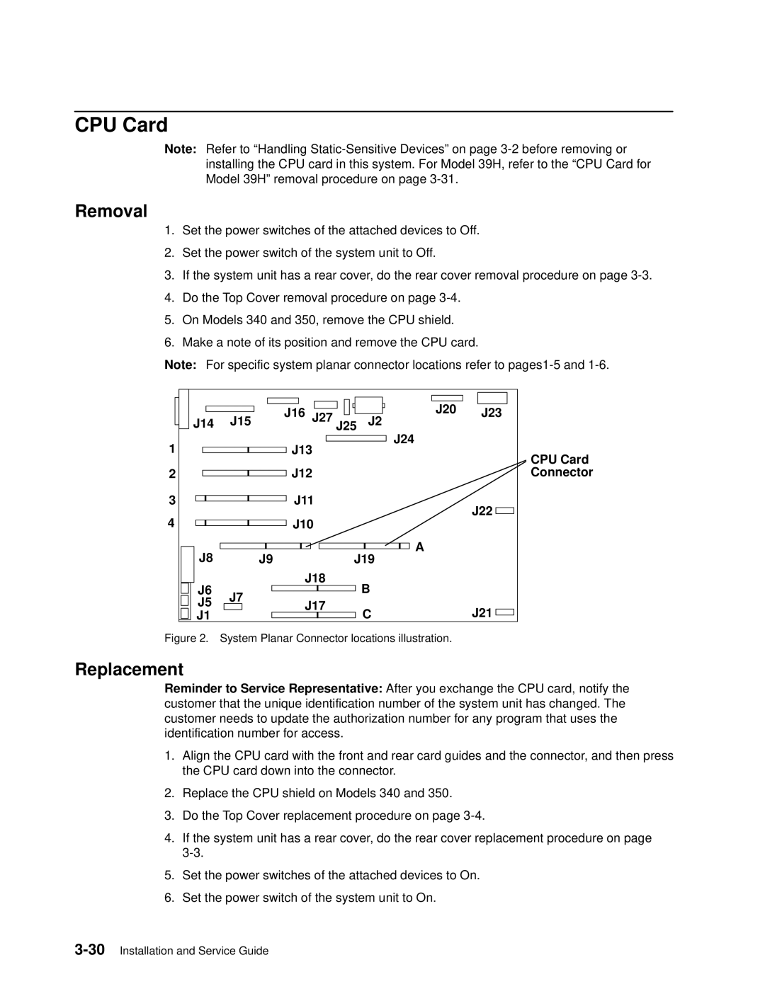
Note: For specific system planar connector locations refer to
| J15 | J16 J27 J25 | J20 | J23 |
J14 | J2 | |||
1 |
| J13 | J24 |
|
|
| CPU Card | ||
|
|
|
| |
2 |
| J12 |
| Connector |
3 |
| J11 |
| J22 |
4 |
| J10 |
| |
|
|
| ||
J8 |
|
| A |
|
J9 | J19 |
| ||
J6 |
| J18 | B |
|
J7 |
|
| ||
J5 | J17 |
|
| |
| C | J21 | ||
J1 |
|
| ||
Figure 2. | System Planar Connector locations illustration. |
| ||
Replacement
Reminder to Service Representative: After you exchange the CPU card, notify the customer that the unique identification number of the system unit has changed. The customer needs to update the authorization number for any program that uses the identification number for access.
1.Align the CPU card with the front and rear card guides and the connector, and then press the CPU card down into the connector.
2.Replace the CPU shield on Models 340 and 350.
3.Do the Top Cover replacement procedure on page
4.If the system unit has a rear cover, do the rear cover replacement procedure on page
5.Set the power switches of the attached devices to On.
6.Set the power switch of the system unit to On.