Top Cover
Note: If the machine is normally operated in the vertical position, it may be helpful to remove the base and proceed with the machine in the horizontal position.
Removal
1.Set the power switches of the attached devices to Off.
2.Set the power switch of the system unit to Off.
3.Disconnect the power cable.
4.Set the key mode switch to the Service position. This unlocks the top cover for removal.
5.If your system unit has a rear cover, do the removal procedure in ªRear Coverº on page
6.Loosen the top cover screws.
Attention: On models 340 and 350, be careful not to damage the contact strip on the right of the power supply.
7.If your system unit has handles, use the handles to slide the top cover to the rear and lift it off.
Attention: Do not operate the system unit with the covers removed. Operating with covers on ensures adequate cooling of the components.
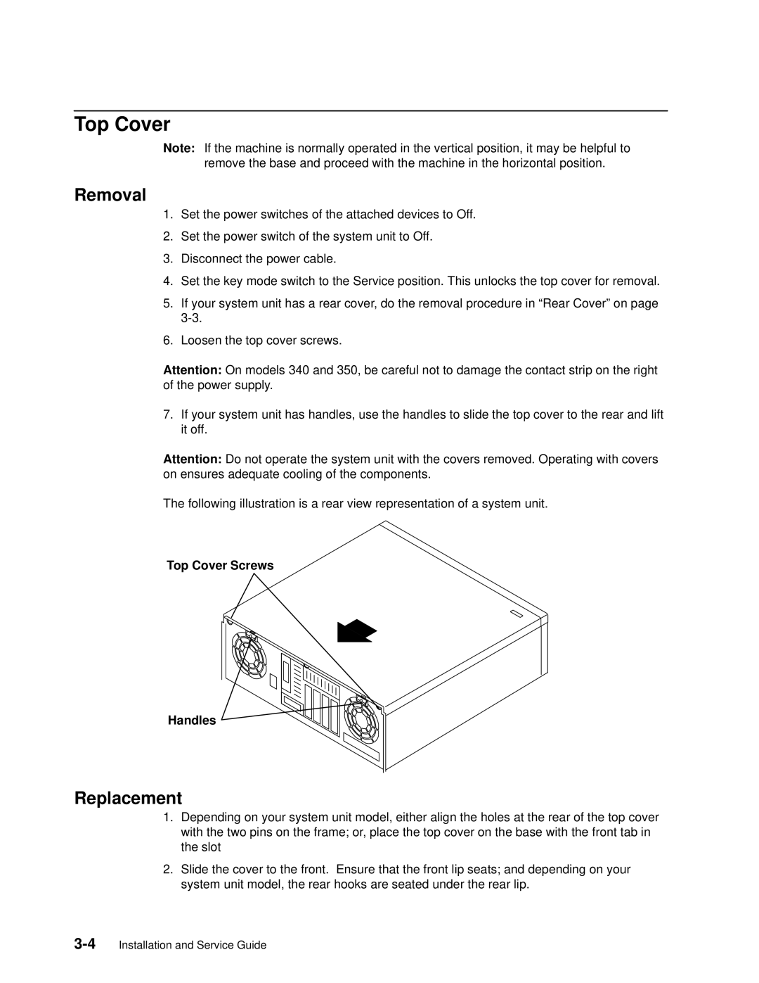
The following illustration is a rear view representation of a system unit.
Top Cover Screws
Handles
Replacement
1.Depending on your system unit model, either align the holes at the rear of the top cover with the two pins on the frame; or, place the top cover on the base with the front tab in the slot
2.Slide the cover to the front. Ensure that the front lip seats; and depending on your system unit model, the rear hooks are seated under the rear lip.