IBM
Edition February
1998
Contents
Menus
Ripl Scsi ID
Scsi
Iv IBM
AIX
Using the Online and Standalone Diagnostics
Aids
ISA
Service
Battery
Test
Index
Commission FCC Statement
Safety Requirements
International Electrotechnical Commission IEC Statement
United
Avis
Statement
Ministère des
Canadian Department of Communications Compliance Statement
Radio Protection for Germany
European Union EU Statement
Electrical Safety
Shock Hazard Disconnect the power cable from
Not serviceable
Safety Information
Laser
Device Not Attempt
Index Part
Power Cables
Index Part Number Country
Xvi IBM RS/6000 7025 F50 Series Users Guide
ISO
Related Publications
Trademarks
Xviii IBM RS/6000 7025 F50 Series Users Guide
System Startup
Begin
Moving the System
Unpacking Your System
Preinstallation Checklist
Machine document
Connecting the Cables
Starting the System
System Startup1-7
Install the Operating System
Install options
Install application programs
Record your identification numbers
Stopping the System Unit
Starting the System Unit
2IBM RS/6000 7025 F50 Series Users Guide
Reading the Operator Panel Display
Keyboards
Using
Using the System2-5Unit
Mouse
Handling the Mouse Correctly
Care of the Mouse
Cleaning the Mouse
Write-Protecting 3.5-Inch Diskettes
Using the 3.5-Inch Diskette Drive Diskette Compatibility
3.5-Inch Diskette
Class
Drive
Covers
As a Unit
CD-ROM Drive
Emergency Eject
Location
Disk Drives
Slot of Scsi Adapter
Label
16IBM RS/6000 7025 F50 Series Users Guide
Labels
Handling Guidelines
Disk Drive Status LED States Scsi Disk Drives
Status LEDs
Button Status
Status Definition
SSA Disk Drives
Types of 8-mm Tape Cartridges
General Information for 8-mm Tape Drive Recommendations
Mode Mm Tape Drive 3GB
Setting the Write-Protect Tab on
Cartridge Compatibility
0GB
Ranges
Environment Considerations for 8-mm Data Cartridges
Tape Cartridge Data Efficiency
Environments
Operating
Mm Data
Status Lights
Using the 5.0GB 8-mm Tape Drive
Ready Busy
Status Light States
Green
Amber
Loading the 8-mm Tape Cartridge
Using the System2-27Unit
Unloading the 8-mm Tape Cartridge
Cleaning the Tape Path on the 5.0GB 8-mm Tape Drive
30IBM RS/6000 7025 F50 Series Users Guide
DDS2
General Information for 4.0GB 4-mm Tape Drive
Types of 4-mm Tape Cartridges
Cleaning Cartridge
Tape Cartridge Compatibility
Device Configuration Non-DDS
Tape
Cartridges
Environmental Considerations for 4-mm Data Cartridges
Data Cartridge Erasure
Tape Cartridge Data Capacity
Environments
Using the 4.0GB 4-mm Tape Drive
LED
Ready
Loading the 4-mm Tape Cartridge
Unloading the 4-mm Tape Cartridge
Path 4.0GB Mm Tape Drive
42IBM RS/6000 7025 F50 Series Users Guide
Graphical System Management Services
System Management Services
2IBM RS/6000 7025 F50 Series Users Guide
Utilities Enables
4IBM RS/6000 7025 F50 Series Users Guide
Config
6IBM RS/6000 7025 F50 Series Users Guide
MultiBoot
Boot
Save
Password
Error Log
Utilities
System Management Services3-11
Password
System Management Services3-13
ReturnsRemotetoOff
Mode
System Management Services3-15
Error Log
Ripl
Again
System Management Services3-19
20IBM RS/6000 7025 F50 Series Users Guide
Scsi ID
You must not turn off System
Update
Precover.img
Firmware Recovery
System
Services
System Management Services3-25
Display Configuration
MultiBoot Menu
Ieee
Boot
System Management Services3-29
Configure Nth Boot Device
Access to Following options
Set Password Unattended Start Mode
Set
Power
Initial
Setup
34IBM RS/6000 7025 F50 Series Users Guide
System Management Services3-35
Full Duplex Yes Auto
Display
Log
Firmware
Select Console
Img
Select Language
40IBM RS/6000 7025 F50 Series Users Guide
Chapter
Service Processor Menus
Service Graphics
Service
Ascii or
Aids Terminals
Menu Inactivity
Service Processor Menus
Locally
Remotely
Power-On System
General User Menus
Read VPD
Read Service Processor Error Logs
Read Progress Indicators from Last System Boot
Read System Post Errors
GMT. AIX
Main Menu
Privileged User Menus
System Name Main Menu
Service Processor Setup Menu
Change Privileged Access Password
Passwords
Change General Access Password
Console Mirroring
Start Talk Mode
Surveillance Delay
Surveillance Setup Menu
Reset
Surveillance
Enable/Disable Unattended Start Mode
Ring Indicator Power-On Menu
Powered-on. TheRing Indicator Power-On Menu
Read VPD Image from Last System Boot
Power-off System
View System Environmental Conditions
Read Nvram
Service Processor4-15Menus
Serial
Port
Serial Port Selection Menu
Number Setup Menu
Port
Menu
Number
Digital
Pager
PIN
Call-Out
Call Out
AndRemote latency
UserID
Customer Account Setup Menu
Policy Setup Menu
OS-Defined restart policy
Service Processor Functions and Features
Error Data Service Processor System Environmental Setup
Start Mode
System Power-On Methods
Operation
Service Processor Reboot/Restart Recovery
Restart
Use OS-Defined restart policy?
YES
Surveillance
Service Processor System Monitoring Surveillance
30IBM RS/6000 7025 F50 Series Users Guide
Call Out Call-Home
Console Mirroring
System Configuration
Service Processor Firmware Updates
File/var/updateflashimage
Shutdown -u /var/\filename\.img
System Post Errors
Safety Considerations
Shock Hazard Disconnect the power cable from
Handling Static-Sensitive Devices
Bays
Expansion Bays
Input/Output Connectors
Only
Installing Options5-7
8IBM RS/6000 7025 F50 Series Users Guide
Installing Options5-9
Removing Both the Front and Side Covers
Installing Options5-11
12IBM RS/6000 7025 F50 Series Users Guide
Installing Options5-13
14IBM RS/6000 7025 F50 Series Users Guide
Installing Options5-15
Planar Cover
Option List
Dimm
Installing Memory
Installing Options5-19
Adapter Cards
Installing
Front
Cards
Installing Options5-23
ECC
Memory-Modules
Adding or Replacing Memory to an Existing Card
26IBM RS/6000 7025 F50 Series Users Guide
Installing Options5-27
Removing Memory
Installing Options5-29
ISA PCI
Installing Adapters
PCI ISA
32IBM RS/6000 7025 F50 Series Users Guide
Installing Options5-33
Removing Adapters
Carefully pull the adapter out of the system
36IBM RS/6000 7025 F50 Series Users Guide
Upgrading or
CPU Card
Hooks
Chapter Installing Options5-39
40IBM RS/6000 7025 F50 Series Users Guide
CD-ROM
Installing Internal Drives
Considerations
Drives
SSA
All Bays
Preinstallation Steps
Tape Drive, or
Bay a
Installing Options5-45
46IBM RS/6000 7025 F50 Series Users Guide
Installing Options5-47
Room
Installing Options5-49
50IBM RS/6000 7025 F50 Series Users Guide
Installing a Scsi Disk Drive in Bank C, D, or E
Install Bank Must Have Hot-swap
Installing Options5-53
54IBM RS/6000 7025 F50 Series Users Guide
Installing a SSA Disk Drive in Bank C, D, or E
Disk Drives are Required
Installing Options5-57
58IBM RS/6000 7025 F50 Series Users Guide
Installing a Scsi Backplane in Bank D or E
Install Backplane Rear
Cable to backplane D Or E as shown
Cable Before connecting
Installing Options5-63
Scsi Adapter
Installing Options5-65
Installing a SSA Backplane in Bank D, or E
Installing Options5-67
68IBM RS/6000 7025 F50 Series Users Guide
Installing Options5-69
70IBM RS/6000 7025 F50 Series Users Guide
Installing Options5-71
72IBM RS/6000 7025 F50 Series Users Guide
Bulkhead Cables Into the three retainers
74IBM RS/6000 7025 F50 Series Users Guide
Installing Options5-75
Attach the new power cable to backplane E
Installing Options5-77
78IBM RS/6000 7025 F50 Series Users Guide
Installing Options5-79
80IBM RS/6000 7025 F50 Series Users Guide
Where Are You Removing Drive? Remove Disk Tape
82IBM RS/6000 7025 F50 Series Users Guide
Removing a Scsi Disk Drive from Bank C, D, or E
84IBM RS/6000 7025 F50 Series Users Guide
Or rough Handling
86IBM RS/6000 7025 F50 Series Users Guide
Removing a SSA Disk Drive from Bank C, D, or E
88IBM RS/6000 7025 F50 Series Users Guide
Blank
90IBM RS/6000 7025 F50 Series Users Guide
Installing a U-Bolt
92IBM RS/6000 7025 F50 Series Users Guide
Replacing the Front Covers
94IBM RS/6000 7025 F50 Series Users Guide
Installing Options5-95
Front
Side Covers
Installing Options5-97
98IBM RS/6000 7025 F50 Series Users Guide
Installing Options5-99
100IBM RS/6000 7025 F50 Series Users Guide
Replacing the I/O Planar Cover
102IBM RS/6000 7025 F50 Series Users Guide
Identifying the Terminal Type to Diagnostics
Standalone and Online Diagnostics Operating Considerations
Selecting a Console Display
Online Standalone
Running Online Diagnostics
Running Standalone Diagnostics
Running the Diagnostics from a TTY Terminal
11/31/41 51/61 Settings
Always
3151 3161/3164
Attributes 11/31/41 51/61 Settings
Setup 3151 3161/3164
Additional Communication Attributes
11/31/41 51/61 Settings Attributes
Setup 31/41 51/61 3164 Attributes Settings
Additional Keyboard Attributes
Keyboard 3151/11 3161
31/41 51/61 3164 Attributes Settings
Additional Printer Attributes
3151/11 3161 Description
Service Mode
Online Diagnostics Modes of Operation
Diagnostic
Diagnostics
10 IBM
Concurrent Mode
Maintenance Mode
Command
Enter the shutdown -m
Running the Standalone Diagnostics
Standalone Diagnostic Operation
Using the Online and Standalone Diagnostics6-13
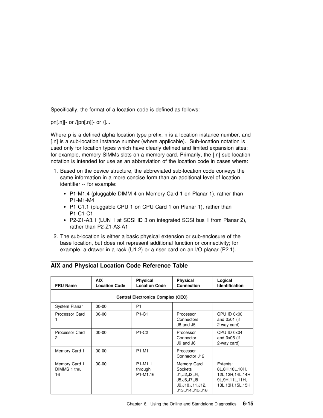
Location Codes
Physical Location Codes
Format
FRU Name
AIX
Location Code
Central
Location Code Connection Identification
Physical Logical
Devices
Pluggable Adapters
Scsi Devices
Physical
FRU
Fans
AB-CD-EF-G,H
AIX Location Codes
Logical FRU Name
Panel
Processor Bus
Memory Dimm in system planar slot
Integrated ISA Adapters
24IBM RS/6000 7025 F50 Series Users Guide
Aids
Update System or Service Processor Flash .Service. . . . Aid
Introduction to Service Aids
Policy
Aid
Using the Service7-5Aids
IBM
Ring
Configure Reboot Policy Service Aid
Configure Surveillance Policy Service Aid
Maximum
Save or Restore Hardware Management Policies Service Aid
Diagnostic Package Utility Service Aid
LFT
Diagnostic Task
Dials and Lpfk Configuration Service Aid
Disk
Disk Based
Version Erase
Disk Maintenance Service Aid
Data Task
Display/Alter
Display Vital
List Task
Add or Delete Drawer Configuration Task
Vital
Add Resource to Resource List Task
Display and Change Diagnostic Test List Service Aid
Scsi Display Configuration Service Aid
Display Test Patterns Service Aid
Results
Dat
Generic Microcode Download Service Aid
Service Aid
Log Task
Microcode Download Service Aid
Machine Check Error Log Service Aid
Optical Disk Service Aids
Bus
Inquiry
Utilities Service Aid
Hints Service Aid
Flash Service Aid
DOS
Display Firmware Device Node
Display Resource Attributes
Chrp
PCI RAID Physical Disk Identify
RAIDant Array Service Aid
26IBM RS/6000 7025 F50 Series Users Guide
Step
This
Considerations
Loading the Diagnostics
Additional System Verification
Running System Verification
Stopping the Diagnostics
This Procedure
Diagnostics
Page
Without any Obvious
Display
Did
Display Action
101-key Keyboard Identify
System Response Action
Menu display?
Terminal?
Instructions display without any obvious display
Considerations before Running This Procedure
Unable to Load Diagnostics
Did the diagnostics load?
E1EB
Symptom Action
101-key Keyboard Identify
Record the Identification Numbers
Appendix A. System Records
Table A-1. Internal and External Options
Device Records
Appendix A. System RecordsA-3
Drive Description
Appendix
Battery, be sure to adhere Following Instructions
Severe burn. Do not recharge
Heat
2IBM RS/6000 7025 F50 Series Users Guide
Command May
4IBM RS/6000 7025 F50 Series Users Guide
Service Processor Setup Checklist
Appendix C. Service Processor Setup and Test
Testing the Setup
Call-In
Call-Out
Serial Port Configuration
4IBM RS/6000 7025 F50 Series Users Guide
File
Files
ATZ
Configuration File Selection
Customizing the Modem Configuration Files
Setup Z Setup Z0 Setup F Setup F0 Setup F1
Examples
Xon/Xoff Modems
Recovery Procedures
Ring Detection
Terminal Emulators
Session
Recovery Strategy
Prevention Strategy
# Componentname Espsetup Entry Service Processor Setup Z
Modem Configuration Samples Sample File modemz.cfg
10IBM RS/6000 7025 F50 Series Users Guide
Sample File modemz0.cfg
Appendix D. Modem ConfigurationsD-11
12IBM RS/6000 7025 F50 Series Users Guide
Sample File modemf.cfg
# Componentname Espsetup Entry Service Processor Setup F
14IBM RS/6000 7025 F50 Series Users Guide
Appendix D. Modem ConfigurationsD-15
RTS
Sample File modemf0.cfg
Appendix D. Modem ConfigurationsD-17
18IBM RS/6000 7025 F50 Series Users Guide
Sample File modemf1.cfg
# Componentname Espsetup Entry Service Processor Setup F1
20IBM RS/6000 7025 F50 Series Users Guide
Appendix D. Modem ConfigurationsD-21
22IBM RS/6000 7025 F50 Series Users Guide
Pre-Standby Phase
Appendix E. Service
SP Post
Processor
Standby Phase
Bring-Up Phase
LCD
Runtime Phase
4IBM RS/6000 7025 F50 Series Users Guide
Numerics
Eprom
Installing Disk drive
Disk Drive from bank C, D, or Tape drive
Retain
CPU
Stby
Index
8IBM RS/6000 7025 F50 Series Users Guide
How satisfied are you
Title Part Number &partnum
This
How Satisfied
10IBM RS/6000 7025 F50 Series Users Guide
Page
IBM