For the setting method, refer to ‘Setting up Areas’ on
Please read the following before getting started
Thank you for purchasing this JVC product
Safety Precautions
For Your Safety Please Read the Following Text Carefully
Blue Neutral Brown Live
For Continental EUROPE, ETC
Safety Precautions
European Union
Business users Other Countries outside the European Union
Safety Precautions
Precautions
Recovery REC, REC INDICATOR, Repeat REC
Weekly Timer Date Timer
Timer Mode
Alarm Search TIME/DATE Search
Maintenance Operation LOG Recording LOG Open Source Status
Rear Terminal
Prealarm Recording
Using the NTP Server Function
Electrical Specifications
List of RS-232C Commands
Main Features
How to Read this Manual
Setting/Canceling the Operation Lock
Setting the Operation Lock
Precautions
Hard Disk Drive
Precautions
„ Place of storage and use
Part Names and Functions Front Panel
„ Return
„ Alarm LED
„ Warning LED
„ HDD LED
„ Spot LED
Part Names and Functions Rear Panel
Part Names and Functions Signal I/O Terminals
Alarm
Alarm Reset
Emergency
EXT REC
System Connection When connecting 9 Cameras
Example
Turning On/Off the Power
Switching the Power On
Switching the Power Off
Menu Screen Operations
Setting up Areas
Language
Time Display Form
Time Zone
Setting the Date/Time
Adjusting the seconds Display with Button Operations
Adjusting the seconds Display with the Signal I/O Terminal
Adjusting the Clock with the NTP Server
Installation Settings
Priority
Duration
Audio REC
Introduction SET-3
Switching between Display Screens
Split Screen
Single Screen
Automatic Single Screen
Changing the Layout of the Split Screens
Press W/X to select the division layout required
Press any of the 1 to 9 buttons
Press the Split button
Setting up monitor output
Sequential
Onscreen Mode
Split Picture
Division a
Division B
Returning to the Monitor Output Selection Mode
Viewing Live Images with Spot Output
Changing Spot Output Manually
Changing Spot Output with Terminal Input on the Rear Panel
Covert Channel
Covert Channel WEB
Select Covert
Playback Permission
Normal Recording Alarm Recording
Timer Recording
Types of Recording
Recording Priority
„ When the EXT REC in is set at Manual
Making Normal Recordings
Making Normal Recording with the EXT REC I/O Terminals
Recording Status Notification
Setting up the Detail REC
Setting the Operation Set
Restrictions on the Settings for Frame Rate
Rate
QTY
Operation Setup Recovery REC, REC INDICATOR, Repeat REC
Procedure for Changing the Number of Cameras
Recovery REC
REC Indicator
Alarm Recording
Setting up the Alarm Terminal
Alarm Recording Signal Input Terminal
Alarm Recording Motion Detection
Setting Alarm Recording
Ending Alarm Recording
Canceling the Alarm with the Button on Front Panel
Canceling the Alarm with the Signal Input Terminal
Using the Motion Detection Function
Motion Detection with Pre-Determined Sensitivity
Normal User
Table #2 Target Area Level and Detection Area Count
Manual Setup
Motion Detection with Freely Determined Sensitivity Levels
Dynamic Sensitivity Level
Target Area Level
Setting up the Motion Detect Area SET
Motion Detection Check Mode
Gray Motion detection disabled
„ Press the -/+ keys to select the scene
Weekly Timer
Buttons Used for Procedures 2. to
Mode
Exec
Date Timer
Activating the Timer Recording Mode
Timer
Settings Start Time
Playing Back during Recording Simultaneous Playback Mode
Pausing during Playback
Playing Back Images
Ending Playback
Switching between Playback Screens
Picture screen.
Six-screen display cannot be activated even if
Press 3 to display the 4 DIV Pattern C screen
Searching with the Alarm List
Alarm
Type EMG
DET
Adjusting Playback Speed Jog/Shuttle Playback
Searching for Images According to Date/ Time
Rotating the Shuttle Dial
Rotating the Jog Dial
Skip Mode
Skipping Recorded Images
Select Skip SET with S/T, and then press the SET button
Skip Play
Enlarging Images Image Zoom
Audio OUT
Double-Size Enlargement
Four-Fold Enlargement
Changing the Onscreen Display Position
Press S/T/W/X
Setting Camera Title
Deleting Characters
One character word will be entered into the camera title
Select Save and press the SET button to save the title
Setting Operation Lock
OPE Lock Release
Operation Lock
REC Stop ALL
Buzzer Setup
Rear Terminal
HDD Full
Selection
Hard Disk Maintenance
Manual Scan Disk
Auto Scan Disk
Precautions When Initializing the Hard Disk
Defrag Database
Initializing the Hard Disk Format
Setting up the Hard Disk for Mirroring
Setting up Mirroring
Canceling Mirroring
Mirroring
Deleting Alarm Lists
Precautions When Setting up Mirroring
Pass Code Setup
Displaying the Power Outage Time List and Log
Deleting the Power Outage List
Displaying the Operation Log and Recording
Rebooting the System
Hard Disk Recovery Feature
Select Reboot with the S/T keys, and then press SET
System will be rebooted
DVD for Recording & Playback Inserting & Removing DVD
DVD-R & DVD-RW Details
VR-509 Export Format
Inserting a DVD
Exporting Data on DVD
TIME/DATE
Delete Method
Export Form
Setting up the Duration setup screen
Press the SET button when all settings have been completed
„ Error Messages
Capacity
Configuration of Completed DVDs
Displays During DVD Export
Points to Note During DVD Export
Permissible Export Format Recording Time
Operations when the Chapter List Screen is Displayed
Possible Operations in the DVD Playback Mode
Returning to the HDD Operation Mode
Playing Back Exported Images on DVD
DVD-Video Format Menus and Playback
Title Menus Chapter Menus
DVD-Video Playback
„ When the flash memory is not acknowledged
This event, select Cancel on the screen and then press SET
Capturing Still Images on the Flash Memory
Disconnect the USB flash memory from the port
Storing Set Data in the Flash Memory
Loading Set Data from the USB Memory
Select Download with S/T, and then press the SET button
Select Upload with S/T, and then press the SET button
Connecting a UPS
External Hard Disk Drives
Minimum PC Specifications Required
Connecting Using a LAN Cable
You Can Do the Following
Setting up a Network for VR-509
Select Host Name with the S/T keys, and then press SET
Select Decision with the W/X keys, and then press SET
Setting up a PC Network
Click on the button
Right-click on My Network, and then select the Properties
Right-click on Properties
Connecting Login to the Network
Displayed if login is successful
Top
Start up the Web browser
Live Image Display
Adding to the Weekly Timer
Changing and Deleting the Weekly Timer
Program List Weekly Timer Setting Screen
Changing the Programs
Adding to the Date Timer
Deleting the Date Timer
Program List Date Timer Setting Screen
Click on Timer Recording → Date Timer
Timer Mode
When the Timer Mode is Deactivated
When the Timer Mode is Activated
Timer Mode will be activated
Alarm Search
Alarm Search Screen
TIME/DATE Search
Playback Image Display
REC Type
Status
Valid Characters
Click on Display → Camera Title in that order
Click on WEB → Covert Channel in that order
Click on your desired checkbox
Mail Notification Setting During Alarm Input
Adjusting Clocks with the NTP Server
Canceling NTP Server Registration
When Clock Synchronization is Successful
When Clock Synchronization Fails
Downloading VR-509 Settings
Downloading procedure will be activated
File Download screen will be displayed
Save AS screen will be displayed
Uploading VR-509 Settings
File Selection screen will be displayed
Display will return to the Upload screen
Upload re-confirmation to VR-509 screen will be displayed
Maintenance
Operation LOG
Recording LOG
Open Source
Setting a Network Address
Registering an Access User
Access User Confirmation Screen
Monitor OUT
Auto Change
Indication
Division PIC
Alarm REC
REC Detail
REC Pattern
Alarm Terminal
Operation
Buzzer
Menu Flowchart
Explanations
Introduction SET Detail REC Detail Operation Live Picture
Camera Disable Select Covert
Menu List
CAM no
Motion Detect SET Dynamic Sensitivity Level
Start DAY
Start Time
4DIVISION 4DIVISION a
4DIVISION B
4DIVISION C
Play Permission
Alarm Count
Alarm Detect
Change Setting
HDD Error
Default Gateway
Alarm List Clear
Timer Control
Host Name
Reboot
Troubleshooting
Maintenance Proceeding
Error
System Rebooted to
HARD-DISK Capacity is Very
Still Picture Failed
Down Data Failed
UP Data Failed
Recording using the Program
Timer
Timer indicator blinks
REC and Play buttons do
Troubleshooting Web Browser
101
Web Browser Glossary
LAN
TCP/IP
NTP
Normal Recording
Record
„ When Alarm Lock is selected
„ When ALL is selected
Repeat Recording
Prealarm Recording
Settings Actual Recording Duration 10 sec
30 sec
60 sec
„ When Event is selected
„ When Time is selected
„ When Alarm is selected
Skip jump
Using the NTP Server Function
Reboot Windows Time Service = Stop → Start
Example net time /setsntp
Activating ActiveX Control and Plug-ins
„ Starting up Internet Explorer
DVD-R/RW Copy
Recording Duration
Repeat Rec off / Audio off
Requirements Upon setup of standard HDD 320 GB 2/2
DVD Recording Time
Time Required for DVD Exporting
Electrical Specifications
Sub 9-pin Connector Specifications
Command Format and ACK/NAK
Sens Commands
List of RS-232C Commands
Basic Table
Details of the Commands
Operation Commands
Alarm FWDB0H BASIC/JVC-1
REV Step AEH BASIC/JVC-1
Event Skip FWD 93H JVC-1
Event Skip REV94H JVC-1
Setup Commands
Sens Commands
Status Sense D7H BASIC/JVC-1
Date Sense BEH BASIC/JVC-1
Time Sense BFH BASIC/JVC-1
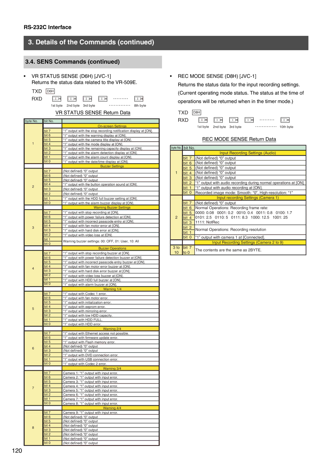
REC Mode Sense D8H JVC-1
VR Status Sense D6H JVC-1
Returns the status data related to the VR-509E
Alarm Mode Sense D9H JVC-1
VR Mode Sense DAH JVC-1
Returns the status data for the operation settings
Monitor Mode Sense DBH JVC-1
Motion Detect Sense DCH JVC-1
1PLAY
Other Commands
Specifications
Index
LAN
REC
VR-509E Digital Video Recorder