KS152JB Universal Communications Controller Technical Specifications
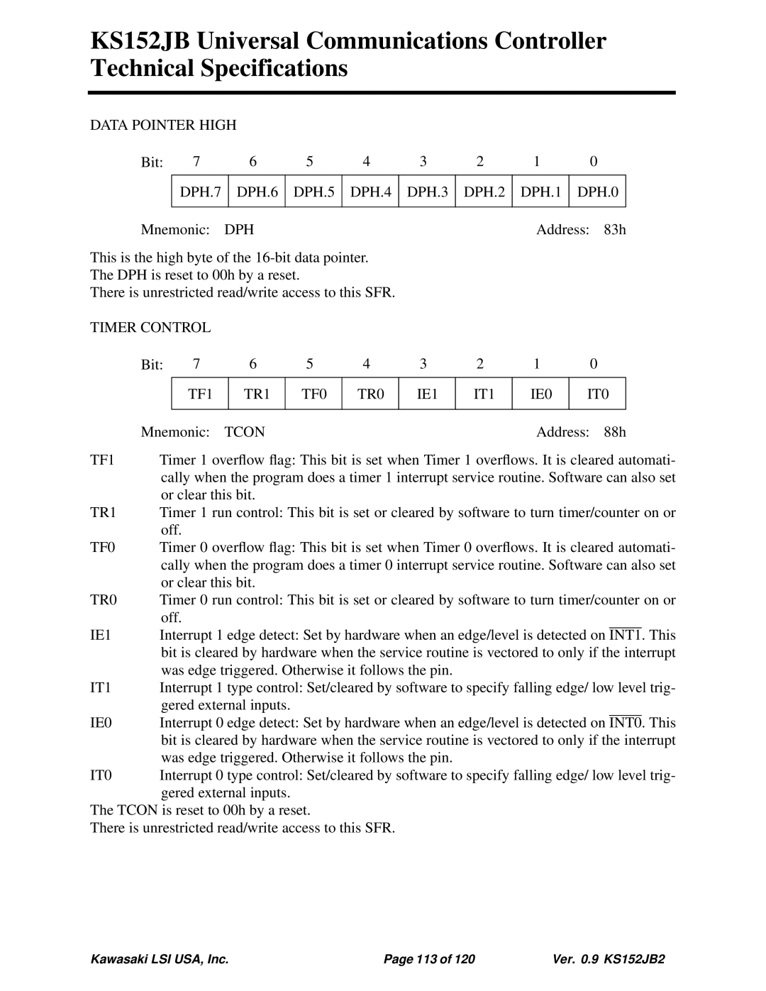
DATA POINTER HIGH |
|
|
|
|
|
|
| |||
Bit: | 7 | 6 | 5 | 4 | 3 | 2 | 1 |
| 0 | |
|
|
|
|
|
|
|
|
| ||
| DPH.7 | DPH.6 | DPH.5 | DPH.4 | DPH.3 | DPH.2 | DPH.1 | DPH.0 | ||
|
|
|
|
|
|
|
|
|
|
|
Mnemonic: | DPH |
|
|
|
| Address: | 83h | |||
This is the high byte of the
The DPH is reset to 00h by a reset.
There is unrestricted read/write access to this SFR.
TIMER CONTROL
| Bit: | 7 | 6 |
| 5 | 4 | 3 | 2 | 1 | 0 |
|
|
| ||
|
|
|
|
|
|
|
|
|
|
|
|
|
| ||
|
|
| TF1 |
| TR1 |
| TF0 | TR0 | IE1 | IT1 | IE0 | IT0 |
|
| |
|
|
|
|
|
|
|
|
|
|
|
|
| |||
| Mnemonic: | TCON |
|
|
|
| Address: 88h | ||||||||
TF1 | Timer 1 overflow flag: This bit is set when Timer 1 overflows. It is cleared automati- | ||||||||||||||
| cally when the program does a timer 1 interrupt service routine. Software can also set | ||||||||||||||
| or clear this bit. |
|
|
|
|
|
|
|
|
| |||||
TR1 | Timer 1 run control: This bit is set or cleared by software to turn timer/counter on or | ||||||||||||||
| off. |
|
|
|
|
|
|
|
|
|
|
|
|
| |
TF0 | Timer 0 overflow flag: This bit is set when Timer 0 overflows. It is cleared automati- | ||||||||||||||
| cally when the program does a timer 0 interrupt service routine. Software can also set | ||||||||||||||
| or clear this bit. |
|
|
|
|
|
|
|
|
| |||||
TR0 | Timer 0 run control: This bit is set or cleared by software to turn timer/counter on or | ||||||||||||||
| off. |
|
|
|
|
|
|
|
|
|
|
|
|
| |
IE1 | Interrupt 1 edge detect: Set by hardware when an edge/level is detected on |
|
| This | |||||||||||
INT1. | |||||||||||||||
| bit is cleared by hardware when the service routine is vectored to only if the interrupt | ||||||||||||||
| was edge triggered. Otherwise it follows the pin. |
|
|
|
|
|
| ||||||||
IT1 | Interrupt 1 type control: Set/cleared by software to specify falling edge/ low level trig- | ||||||||||||||
| gered external inputs. |
|
|
|
|
|
|
|
|
| |||||
IE0 | Interrupt 0 edge detect: Set by hardware when an edge/level is detected on |
|
| This | |||||||||||
INT0. | |||||||||||||||
| bit is cleared by hardware when the service routine is vectored to only if the interrupt | ||||||||||||||
| was edge triggered. Otherwise it follows the pin. |
|
|
|
|
|
| ||||||||
IT0 | Interrupt 0 type control: Set/cleared by software to specify falling edge/ low level trig- | ||||||||||||||
| gered external inputs. |
|
|
|
|
|
|
|
|
| |||||
The TCON is reset to 00h by a reset.
There is unrestricted read/write access to this SFR.
Kawasaki LSI USA, Inc. | Page 113 of 120 | Ver. 0.9 KS152JB2 |