KS152JB Universal Communications Controller Technical Specifications
During External Memory Accesses, both Ports 0 and 2 are used for Address/ Data transfer and therefore cannot be used for general I/O purposes. During external program fetches, Port 2 uses strong pullups to emit 1s.
2.7 TIMER/COUNTERS
This has two
When configured as a “Timer”, the register is incremented once every machine cycle. Since a machine cycle consists of 12 clock periods, the timer clock can be thought of as 1/12 of the master clock. In the “Counter” mode, the register is incremented on the falling edge of the external input pin, T0 in case of TM0, T1 for TM1. The T0, T1 inputs are sampled in every machine cycle at S5P2. If the sampled value is high in one machine cycle and low in the next, then a valid high to low transition on the pin is recognized and the count register is incremented. Since it takes two machine cycles to recognize a negative transition on the pin, the maximum rate at which counting will take place is 1/24 of the master clock frequency. In either the “Timer” or “Counter” mode, the count register will be updated in S3P1. Therefore, in the “Timer” mode, the recognized negative transition on pin T0 and T1 can cause the count register value to be updated only in the machine cycle following the one in which the negative edge was detected.
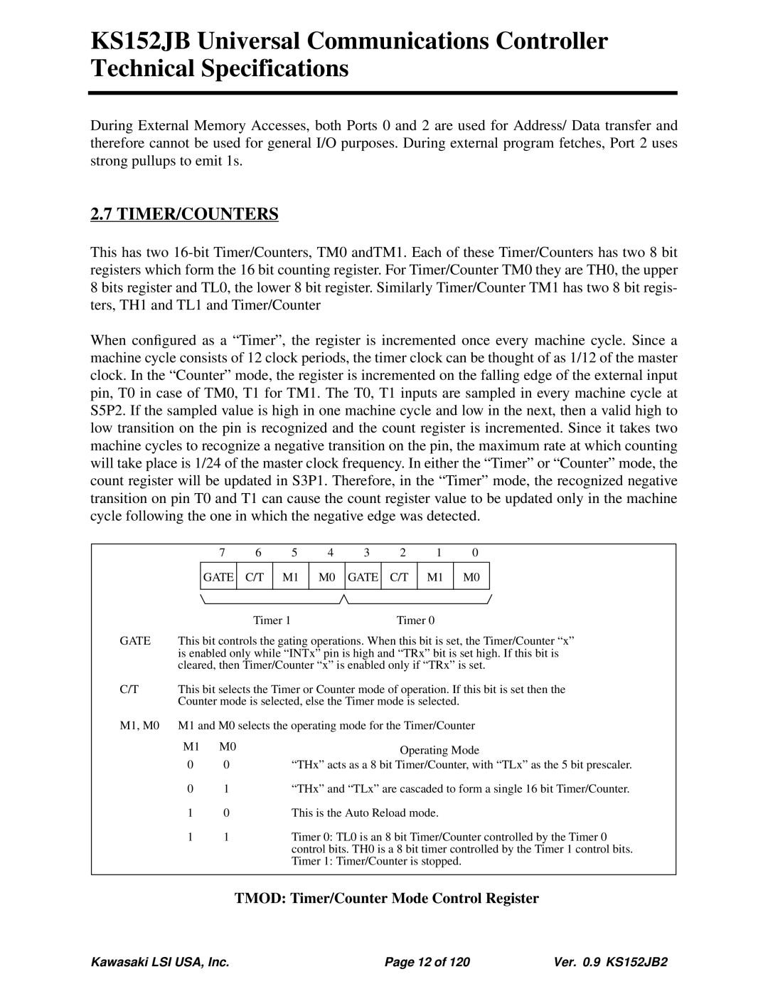
7 | 6 | 5 | 4 | 3 | 2 | 1 | 0 |
GATE
C/T
M1
M0
GATE
C/T
M1
M0
|
| Timer 1 | Timer 0 |
GATE | This bit controls the gating operations. When this bit is set, the Timer/Counter “x” | ||
| is enabled only while “INTx” pin is high and “TRx” bit is set high. If this bit is | ||
| cleared, then Timer/Counter “x” is enabled only if “TRx” is set. | ||
C/T | This bit selects the Timer or Counter mode of operation. If this bit is set then the | ||
| Counter mode is selected, else the Timer mode is selected. | ||
M1, M0 | M1 and M0 selects the operating mode for the Timer/Counter | ||
| M1 | M0 | Operating Mode |
|
|
| |
| 0 | 0 | “THx” acts as a 8 bit Timer/Counter, with “TLx” as the 5 bit prescaler. |
| 0 | 1 | “THx” and “TLx” are cascaded to form a single 16 bit Timer/Counter. |
| 1 | 0 | This is the Auto Reload mode. |
| 1 | 1 | Timer 0: TL0 is an 8 bit Timer/Counter controlled by the Timer 0 |
|
|
| control bits. TH0 is a 8 bit timer controlled by the Timer 1 control bits. |
|
|
| Timer 1: Timer/Counter is stopped. |
TMOD: Timer/Counter Mode Control Register
Kawasaki LSI USA, Inc. | Page 12 of 120 | Ver. 0.9 KS152JB2 |