KS152JB Universal Communications Controller Technical Specifications
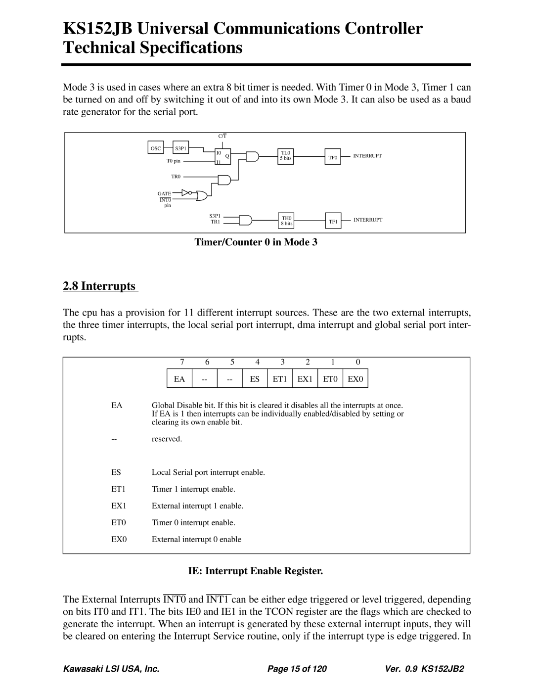
Mode 3 is used in cases where an extra 8 bit timer is needed. With Timer 0 in Mode 3, Timer 1 can be turned on and off by switching it out of and into its own Mode 3. It can also be used as a baud rate generator for the serial port.
OSC |
| S3P1 |
C/T
T0 pin
TR0
GATE ![]()
![]()
INT0 pin
I0
I1
S3P1
TR1
Q
TL0
5 bits
TH0
8 bits
TF0
TF1
INTERRUPT
INTERRUPT
Timer/Counter 0 in Mode 3
2.8 Interrupts
The cpu has a provision for 11 different interrupt sources. These are the two external interrupts, the three timer interrupts, the local serial port interrupt, dma interrupt and global serial port inter- rupts.
| 7 | 6 | 5 |
| 4 | 3 | 2 | 1 | 0 |
| |
|
|
|
|
|
|
|
|
|
|
|
|
|
| EA |
| ES | ET1 | EX1 | ET0 | EX0 |
| ||
|
|
|
|
|
|
|
|
|
|
| |
EA | Global Disable bit. If this bit is cleared it disables all the interrupts at once. | ||||||||||
| If EA is 1 then interrupts can be individually enabled/disabled by setting or | ||||||||||
| clearing its own enable bit. |
|
|
|
|
|
| ||||
reserved. |
|
|
|
|
|
|
|
|
| ||
ES | Local Serial port interrupt enable. |
|
|
|
|
| |||||
ET1 | Timer 1 interrupt enable. |
|
|
|
|
|
| ||||
EX1 | External interrupt 1 enable. |
|
|
|
|
|
| ||||
ET0 | Timer 0 interrupt enable. |
|
|
|
|
|
| ||||
EX0 | External interrupt 0 enable |
|
|
|
|
|
| ||||
|
|
|
|
|
|
|
|
|
|
|
|
IE: Interrupt Enable Register.
The External Interrupts INT0 and INT1 can be either edge triggered or level triggered, depending on bits IT0 and IT1. The bits IE0 and IE1 in the TCON register are the flags which are checked to generate the interrupt. When an interrupt is generated by these external interrupt inputs, they will be cleared on entering the Interrupt Service routine, only if the interrupt type is edge triggered. In
Kawasaki LSI USA, Inc. | Page 15 of 120 | Ver. 0.9 KS152JB2 |