KS152JB Universal Communications Controller Technical Specifications
3.3 SDLC Operation
SDLC is a communication protocol developed by IBM and widely used in industry. It is based on a primary/ secondary architecture and requires that each secondary station have a unique address. The secondary stations can only communicate to the primary station, and then, only when the pri- mary station allows communication to take place. This eliminates the possibility of contention on the serial line caused by the secondary station’s trying to transmit simultaneously.
In the C152, SDLC can be configured to work in either full or half duplex. When adhering to strict SDLC protocol, full duplex is required. Full duplex is selected whenever a
3.3.2 SDLC Frame Format
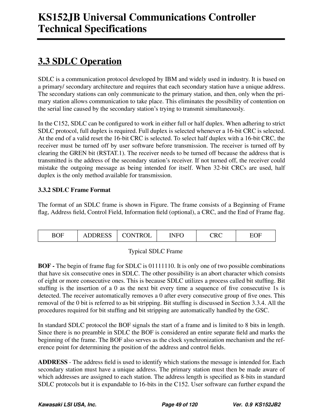
The format of an SDLC frame is shown in Figure. The frame consists of a Beginning of Frame flag, Address field, Control Field, Information field (optional), a CRC, and the End of Frame flag.
BOF
ADDRESS
CONTROL
INFO
CRC
EOF
Typical SDLC Frame
BOF - The begin of frame flag for SDLC is 01111110. It is only one of two possible combinations that have six consecutive ones in SDLC. The other possibility is an abort character which consists of eight or more consecutive ones. This is because SDLC utilizes a process called bit stuffing. Bit stuffing is the insertion of a 0 as the next bit every time a sequence of five consecutive 1s is detected. The receiver automatically removes a 0 after every consecutive group of five ones. This removal of the 0 bit is referred to as bit stripping. Bit stuffing is discussed in Section 3.3.4. All the procedures required for bit stuffing and bit stripping are automatically handled by the GSC.
In standard SDLC protocol the BOF signals the start of a frame and is limited to 8 bits in length. Since there is no preamble in SDLC the BOF is considered an entire separate field and marks the beginning of the frame. The BOF also serves as the clock synchronization mechanism and the ref- erence point for determining the position of the address and control fields.
ADDRESS - The address field is used to identify which stations the message is intended for. Each secondary station must have a unique address. The primary station must then be made aware of which addresses are assigned to each station. The address length is specified as
Kawasaki LSI USA, Inc. | Page 49 of 120 | Ver. 0.9 KS152JB2 |