KS152JB Universal Communications Controller Technical Specifications
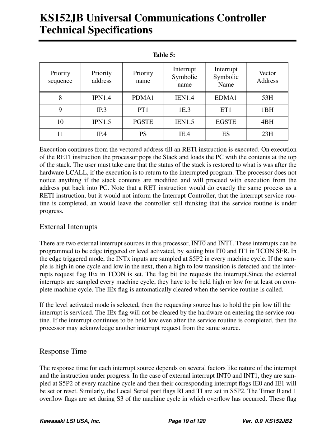
Table 5:
Priority | Priority | Priority | Interrupt | Interrupt | Vector | |
Symbolic | Symbolic | |||||
sequence | address | name | Address | |||
name | Name | |||||
|
|
|
| |||
|
|
|
|
|
| |
|
|
|
|
|
| |
8 | IPN1.4 | PDMA1 | IEN1.4 | EDMA1 | 53H | |
|
|
|
|
|
| |
9 | IP.3 | PT1 | 1E.3 | ET1 | 1BH | |
|
|
|
|
|
| |
10 | IPN1.5 | PGSTE | IEN1.5 | EGSTE | 4BH | |
|
|
|
|
|
| |
11 | IP.4 | PS | IE.4 | ES | 23H | |
|
|
|
|
|
|
Execution continues from the vectored address till an RETI instruction is executed. On execution of the RETI instruction the processor pops the Stack and loads the PC with the contents at the top of the stack. The user must take care that the status of the stack is restored to what is was after the hardware LCALL, if the execution is to return to the interrupted program. The processor does not notice anything if the stack contents are modified and will proceed with execution from the address put back into PC. Note that a RET instruction would do exactly the same process as a RETI instruction, but it would not inform the Interrupt Controller, that the interrupt service rou- tine is completed, an would leave the controller still thinking that the service routine is under progress.
External Interrupts
There are two external interrupt sources in this processor, INT0 and INT1. These interrupts can be programmed to be edge triggered or level activated, by setting bits IT0 and IT1 in TCON SFR. In the edge triggered mode, the INTx inputs are sampled at S5P2 in every machine cycle. If the sam- ple is high in one cycle and low in the next, then a high to low transition is detected and the inter- rupts request flag IEx in TCON is set. The flag bit the requests the interrupt.Since the external interrupts are sampled every machine cycle, they have to be held high or low for at least on com- plete machine cycle. The IEx flag is automatically cleared when the service routine is called.
If the level activated mode is selected, then the requesting source has to hold the pin low till the interrupt is serviced. The IEx flag will not be cleared by the hardware on entering the service rou- tine. If the interrupt continues to be held low even after the service routine is completed, then the processor may acknowledge another interrupt request from the same source.
Response Time
The response time for each interrupt source depends on several factors like nature of the interrupt and the instruction under progress. In the case of external interrupt INT0 and INT1, they are sam- pled at S5P2 of every machine cycle and then their corresponding interrupt flags IE0 and IE1 will be set or reset. Similarly, the Local Serial port flags RI and TI are set in S5P2. The Timer 0 and 1 overflow flags are set during S3 of the machine cycle in which overflow has occurred. These flag
Kawasaki LSI USA, Inc. | Page 19 of 120 | Ver. 0.9 KS152JB2 |