KS152JB Universal Communications Controller Technical Specifications
|
| Table 14: | |
|
|
|
|
Interrupt | Location |
| Name |
|
|
|
|
|
|
|
|
DMA1 | 0053H |
| DMA Channel 1 Done |
|
|
|
|
TF1 | 001BH |
| Timer 1 Overflow |
|
|
|
|
GSCTE | 004BH |
| GSC Transmit Error |
|
|
|
|
TI+RI | 0023H |
| UART Transmit/Receive |
|
|
|
|
Note that the locations of the basic 8051 interrupts are the same as in the rest of the
The locations of the new interrupts all follow the locations the basic 8051 interrupts in the Pro- gram Memory, but they are interleaved with them in the polling sequence.
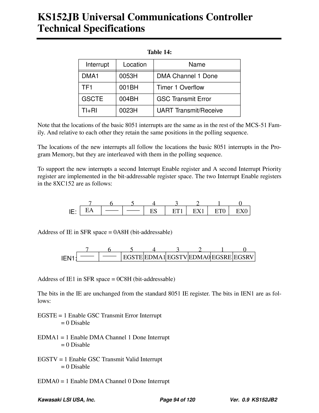
To support the new interrupts a second Interrupt Enable register and A second Interrupt Priority register are implemented in the
IE:
7 | 6 |
| 5 |
| 4 | 3 | 2 | 1 | 0 | ||
EA |
|
|
|
|
|
| ES | ET1 | EX1 | ET0 | EX0 |
|
|
|
|
|
| ||||||
|
|
|
|
|
|
|
|
|
|
|
|
Address of IE in SFR space = 0A8H
7 |
| 6 |
| 5 | 4 | 3 | 2 | 1 | 0 | |||
IEN1: |
|
|
|
|
|
| EGSTE | EDMA1 | EGSTV | EDMA0 | EGSRE | EGSRV |
|
|
|
|
|
| |||||||
Address of IE1 in SFR space = 0C8H
The bits in the IE are unchanged from the standard 8051 IE register. The bits in IEN1 are as fol- lows:
EGSTE = 1 Enable GSC Transmit Error Interrupt
= 0 Disable
EDMA1 = 1 Enable DMA Channel 1 Done Interrupt
= 0 Disable
EGSTV = 1 Enable GSC Transmit Valid Interrupt
= 0 Disable
EDMA0 = 1 Enable DMA Channel 0 Done Interrupt
Kawasaki LSI USA, Inc. | Page 94 of 120 | Ver. 0.9 KS152JB2 |