KS152JB Universal Communications Controller Technical Specifications
DMA CHANNEL 0
DARHO | DARLO |
DESTINATION ADDRESS
SARHO | SARLO |
SOURCE ADDRESS
BCRHO
BCRLO
BYTE COUNT
DCONO
DMAO CONTROL PCON
DMA CHANNEL 1
DARH1 |
|
| DARL1 |
|
|
|
|
|
|
| |
DESTINATION ADDRESS | |||||
|
|
|
|
|
|
SARH1 |
|
| SARL1 |
|
|
|
|
|
|
| |
SOURCE ADDRESS | |||||
|
|
|
|
|
|
BCRH1 |
|
| BCRL1 |
| |
|
|
|
|
|
|
BYTE COUNT
DCON1
DMA1 CONTROL
Two new bits in PCON control
Hold/Hold Acknowledge logic
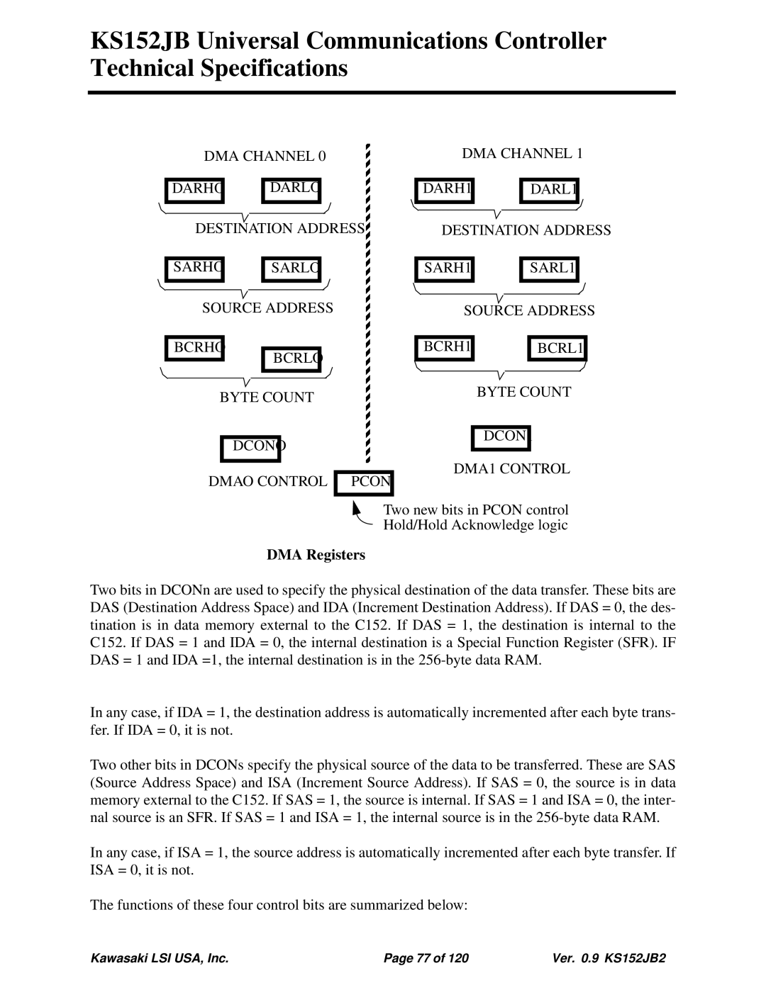
DMA Registers
Two bits in DCONn are used to specify the physical destination of the data transfer. These bits are DAS (Destination Address Space) and IDA (Increment Destination Address). If DAS = 0, the des- tination is in data memory external to the C152. If DAS = 1, the destination is internal to the C152. If DAS = 1 and IDA = 0, the internal destination is a Special Function Register (SFR). IF DAS = 1 and IDA =1, the internal destination is in the
In any case, if IDA = 1, the destination address is automatically incremented after each byte trans- fer. If IDA = 0, it is not.
Two other bits in DCONs specify the physical source of the data to be transferred. These are SAS (Source Address Space) and ISA (Increment Source Address). If SAS = 0, the source is in data memory external to the C152. If SAS = 1, the source is internal. If SAS = 1 and ISA = 0, the inter- nal source is an SFR. If SAS = 1 and ISA = 1, the internal source is in the
In any case, if ISA = 1, the source address is automatically incremented after each byte transfer. If ISA = 0, it is not.
The functions of these four control bits are summarized below:
Kawasaki LSI USA, Inc. | Page 77 of 120 | Ver. 0.9 KS152JB2 |