KS152JB Universal Communications Controller Technical Specifications
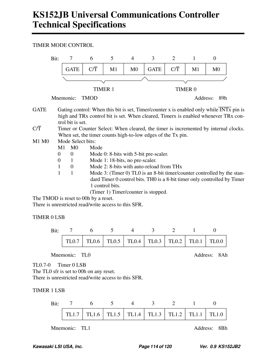
TIMER MODE CONTROL |
|
|
|
|
|
|
|
|
|
|
|
|
| |||||||||
|
|
| Bit: | 7 | 6 |
|
| 5 | 4 | 3 |
| 2 |
|
|
| 1 | 0 |
|
|
| ||
|
|
|
|
|
|
|
|
|
|
|
|
|
|
|
|
|
|
|
| |||
|
|
|
|
| GATE |
|
|
|
| M1 | M0 | GATE |
|
|
|
|
| M1 | M0 |
|
| |
|
|
|
|
|
| C/T |
|
| C/T |
|
| |||||||||||
|
|
|
|
|
|
|
|
|
|
|
|
|
|
|
|
|
|
|
| |||
|
|
|
|
|
|
| TIMER 1 |
|
|
| TIMER 0 |
|
|
|
| |||||||
|
|
| Mnemonic: | TMOD |
|
|
|
|
|
|
|
| Address: 89h | |||||||||
GATE | Gating control: When this bit is set, Timer/counter x is enabled only while |
|
| pin is | ||||||||||||||||||
INTx | ||||||||||||||||||||||
|
|
| high and TRx control bit is set. When cleared, Timerx is enabled whenever TRx con- | |||||||||||||||||||
|
|
| trol bit is set. |
|
|
|
|
|
|
|
|
|
|
|
|
| ||||||
|
|
| Timer or Counter Select: When cleared, the timer is incremented by internal clocks. | |||||||||||||||||||
C/T |
| |||||||||||||||||||||
|
|
| When set, the timer counts |
|
|
|
|
| ||||||||||||||
M1 M0 | Mode Select bits: |
|
|
|
|
|
|
|
|
|
|
|
|
| ||||||||
|
|
| M1 | M0 |
| Mode |
|
|
|
|
|
|
|
|
|
|
|
|
| |||
|
|
| 0 |
| 0 |
| Mode 0: |
|
|
|
|
|
|
|
|
| ||||||
01 Mode 1:
10 Mode 2:
1 |
| 1 |
| Mode 3: (Timer 0) TL0 is an | |||||||||
|
|
|
| dard Timer 0 control bits. TH0 is a | |||||||||
|
|
|
| 1 control bits. |
|
|
|
|
|
|
|
| |
|
|
|
| (Timer 1) Timer/counter is stopped. |
|
|
|
|
| ||||
The TMOD is reset to 00h by a reset. |
|
|
|
|
|
|
|
| |||||
There is unrestricted read/write access to this SFR. |
|
|
|
|
|
|
| ||||||
TIMER 0 LSB |
|
|
|
|
|
|
|
|
|
|
|
| |
Bit: | 7 | 6 | 5 | 4 | 3 |
| 2 | 1 |
| 0 |
| ||
|
|
|
|
|
|
|
|
|
|
|
|
| |
|
| TL0.7 |
| TL0.6 | TL0.5 | TL0.4 | TL0.3 |
| TL0.2 | TL0.1 | TL0.0 |
| |
|
|
|
|
|
|
|
|
|
|
|
|
| |
Mnemonic: | TL0 |
|
|
|
|
| Address: | 8Ah | |||||
|
|
|
|
|
|
|
|
| |||||
The TL0 sfr is set to 00h on any reset. |
|
|
|
|
|
|
|
| |||||
There is unrestricted read/write access to this SFR. |
|
|
|
|
|
|
| ||||||
TIMER 1 LSB |
|
|
|
|
|
|
|
|
|
|
|
| |
Bit: | 7 | 6 | 5 | 4 | 3 |
| 2 | 1 |
| 0 |
| ||
|
|
|
|
|
|
|
|
|
|
| |||
|
| TL1.7 |
| TL1.6 | TL1.5 | TL1.4 | TL1.3 |
| TL1.2 | TL1.1 | TL1.0 |
| |
|
|
|
|
|
|
|
|
|
|
|
|
| |
Mnemonic: | TL1 |
|
|
|
|
| Address: | 8Bh | |||||
Kawasaki LSI USA, Inc. | Page 114 of 120 | Ver. 0.9 KS152JB2 |