KS152JB Universal Communications Controller Technical Specifications
2.9 Power Down and Idle
The processor has two Power Reduction modes, Idle and Power Down. Backup power is supplied through the VCC pin in these operations. The processor can be put into the Idle or the Power down mode by setting bits 0 or bit 1 respectively in the PCON SFR.
Any instruction sets the PD bit in PCON SFR, causes that instruction to be the last instruction executed by the processor before going into the Power Down mode. In the Power Down mode, the clock to the CPU and the peripheral blocks like Interrupt Controller, Serial Port, dma and Timer/ Counters is stopped. This causes the complete processor to stop its current activities. The status of all the registers in the CPU, the ALU, the Program Counter, the Stack Pointer, the Program status Word and the Accumulator are held at their current states. The port pins hold the value they had at the time Idle was activated. ALE and PSEN are both held at logic low levels.
There are two ways to exit from the Power Down mode. One is a hardware reset. reset and the other an external interrupt. The hardware reset redefines all the SFRs but the
With an external interrupt, INT0 or INT1 must be enabled and configures as level triggered inter- rupts before entering the power down mode. Holding the pin low ends the power down mode con- dition and bringing the pin high completes the exit. After the interrupt service routine is executed the program will return to the next instruction following the one that put the device into Power Down Mode.
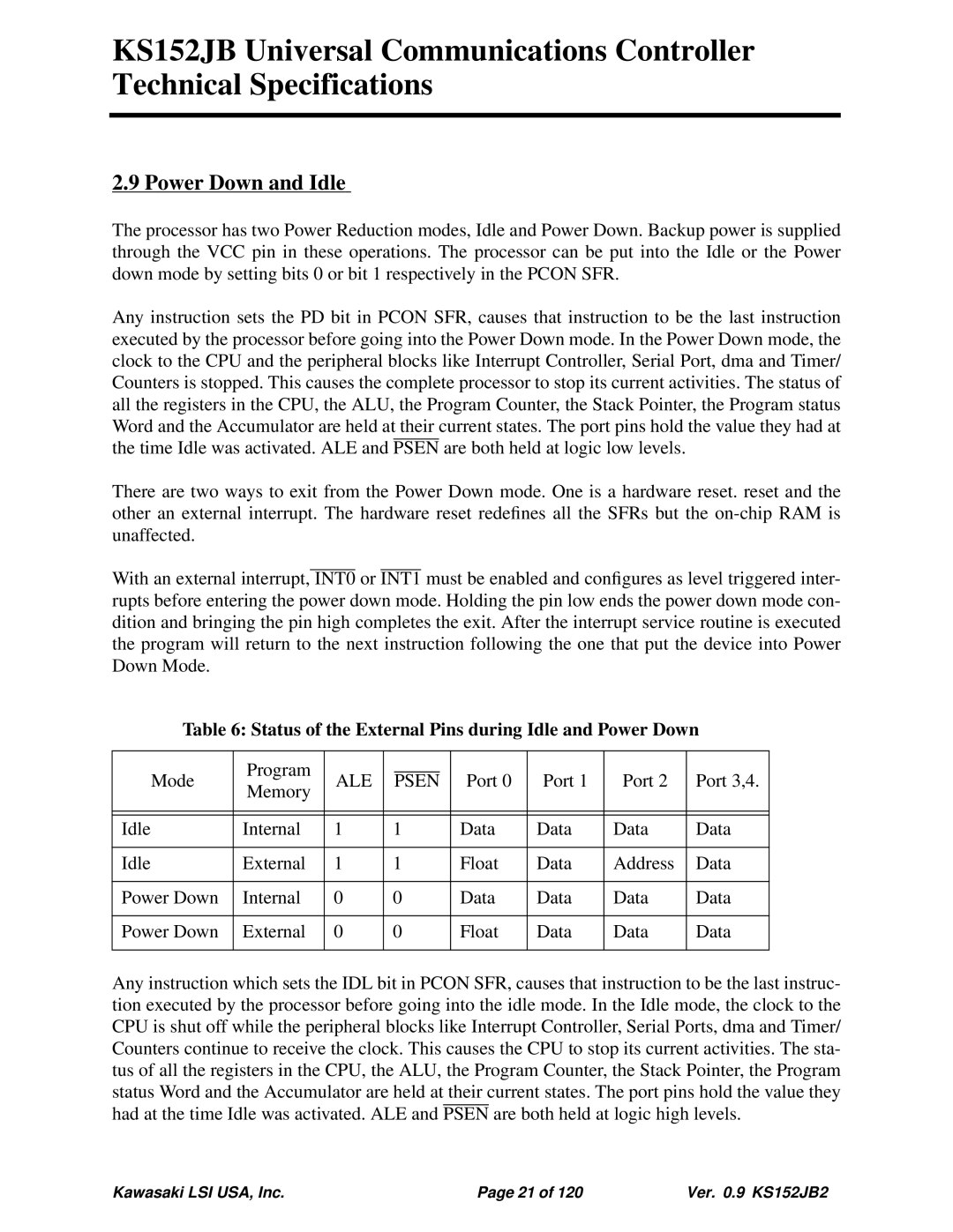
Table 6: Status of the External Pins during Idle and Power Down
| Program |
|
|
|
|
|
|
|
|
Mode | ALE |
| PSEN |
| Port 0 | Port 1 | Port 2 | Port 3,4. | |
Memory |
|
| |||||||
|
|
|
|
|
|
|
|
| |
|
|
|
|
|
|
|
|
| |
|
|
|
|
|
|
|
|
| |
Idle | Internal | 1 | 1 |
| Data | Data | Data | Data | |
|
|
|
|
|
|
|
|
| |
Idle | External | 1 | 1 |
| Float | Data | Address | Data | |
|
|
|
|
|
|
|
|
| |
Power Down | Internal | 0 | 0 |
| Data | Data | Data | Data | |
|
|
|
|
|
|
|
|
| |
Power Down | External | 0 | 0 |
| Float | Data | Data | Data | |
|
|
|
|
|
|
|
|
|
|
Any instruction which sets the IDL bit in PCON SFR, causes that instruction to be the last instruc- tion executed by the processor before going into the idle mode. In the Idle mode, the clock to the CPU is shut off while the peripheral blocks like Interrupt Controller, Serial Ports, dma and Timer/ Counters continue to receive the clock. This causes the CPU to stop its current activities. The sta- tus of all the registers in the CPU, the ALU, the Program Counter, the Stack Pointer, the Program status Word and the Accumulator are held at their current states. The port pins hold the value they had at the time Idle was activated. ALE and PSEN are both held at logic high levels.
Kawasaki LSI USA, Inc. | Page 21 of 120 | Ver. 0.9 KS152JB2 |