4059-XXX
Configuration 1
A level 1 fuser board and level 1 engine board are installed in configuration 1.
Note: Check the fuser envelope conditioner solenoid adjustment as described in the adjustment section “Fuser Solenoid Adjustment” on page
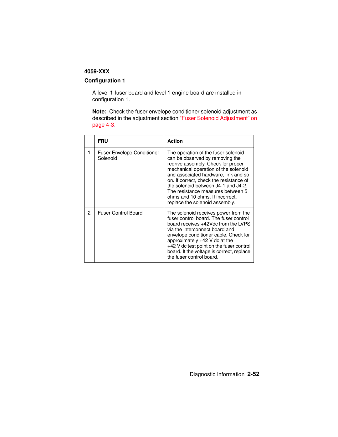
| FRU | Action |
|
|
|
1 | Fuser Envelope Conditioner | The operation of the fuser solenoid |
| Solenoid | can be observed by removing the |
|
| redrive assembly. Check for proper |
|
| mechanical operation of the solenoid |
|
| and associated hardware, link and so |
|
| on. If correct, check the resistance of |
|
| the solenoid between |
|
| The resistance measures between 5 |
|
| ohms and 10 ohms. If incorrect, |
|
| replace the solenoid assembly. |
|
|
|
2 | Fuser Control Board | The solenoid receives power from the |
|
| fuser control board. The fuser control |
|
| board receives +42Vdc from the LVPS |
|
| via the interconnect board and |
|
| envelope conditioner cable. Check for |
|
| approximately +42 V dc at the |
|
| +42 V dc test point on the fuser control |
|
| board. If the voltage is correct, replace |
|
| the fuser control board. |
|
|
|
