4059-XXX
Configuration 3
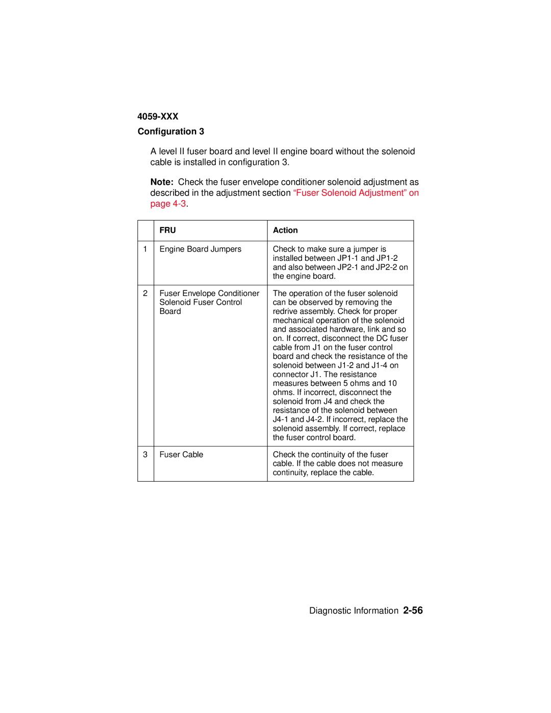
A level II fuser board and level II engine board without the solenoid cable is installed in configuration 3.
Note: Check the fuser envelope conditioner solenoid adjustment as described in the adjustment section “Fuser Solenoid Adjustment” on page
| FRU | Action |
|
|
|
1 | Engine Board Jumpers | Check to make sure a jumper is |
|
| installed between |
|
| and also between |
|
| the engine board. |
|
|
|
2 | Fuser Envelope Conditioner | The operation of the fuser solenoid |
| Solenoid Fuser Control | can be observed by removing the |
| Board | redrive assembly. Check for proper |
|
| mechanical operation of the solenoid |
|
| and associated hardware, link and so |
|
| on. If correct, disconnect the DC fuser |
|
| cable from J1 on the fuser control |
|
| board and check the resistance of the |
|
| solenoid between |
|
| connector J1. The resistance |
|
| measures between 5 ohms and 10 |
|
| ohms. If incorrect, disconnect the |
|
| solenoid from J4 and check the |
|
| resistance of the solenoid between |
|
| |
|
| solenoid assembly. If correct, replace |
|
| the fuser control board. |
|
|
|
3 | Fuser Cable | Check the continuity of the fuser |
|
| cable. If the cable does not measure |
|
| continuity, replace the cable. |
|
|
|
