OPERATION
Return to Section TOC
WELDING OPERATION
GENERAL INFORMATION
WARNING
• Do not touch electrically live parts or elec- trodes with your skin or wet clothing.
![]() • Do not breathe welding fumes or gases.
• Do not breathe welding fumes or gases.
• Use ventilation or exhaust to remove welding fumes from the breathing area.
To use the RANGER
1.Remove the flange nuts from output terminals and place the work and electrode welding cables over the terminals. See Figure B.4. Replace and tight- en the flange nuts securely. Be sure the connec- tions are tight.
2.Select the appropriate electrode. See “Welding Tips 1” included with your RANGER
3.Attach the work clamp securely to the work you are welding.
4.Insert the electrode into the electrode holder.
5.Set the IDLER CONTROL to AUTO and start the diesel engine. See Engine Operation in this sec- tion of the manual.
Return to Section TOC
Section TOC
Return to Master TOC
Return to Master TOC
Master TOC
![]()
![]()
![]() • Keep flammable material away.
• Keep flammable material away.
• Wear eye, ear, and body protection.
The RANGER
6.Set the OUTPUT RANGE dial to a setting equal to or slightly higher than the welding current recom- mended for the electrode being used.
7.Set the POLARITY SWITCH to the desired polarity.
8.Set the FINE OUTPUT CONTROL. Use a setting that results in the highest output at the lowest set- ting of the RANGE switch for the application.
9.Strike an arc and begin welding.
After you finish welding:
1.Stop the diesel engine. See Engine Operation in this section of the manual.
2.Allow the electrode and work to cool completely.
3.Remove the work clamp from the work.
4.Remove any remaining piece of electrode from the electrode holder.
5.If you are finished using the RANGER
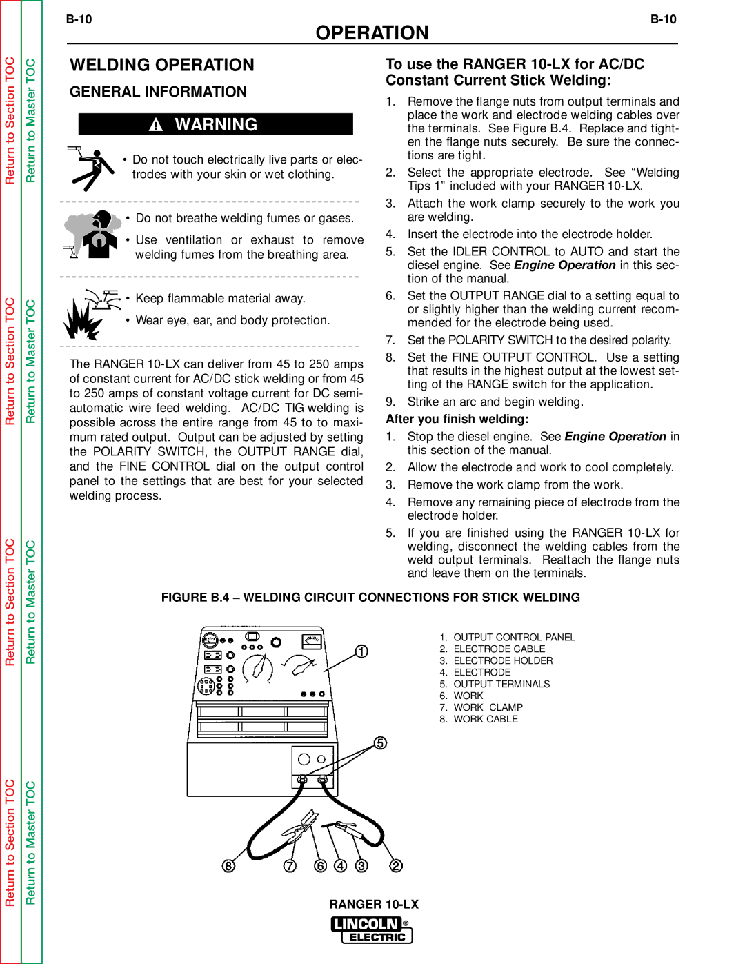
FIGURE B.4 – WELDING CIRCUIT CONNECTIONS FOR STICK WELDING
1. OUTPUT CONTROL PANEL
2. ELECTRODE CABLE
3. ELECTRODE HOLDER
4. ELECTRODE
5. OUTPUT TERMINALS
6. WORK
7. WORK CLAMP
8. WORK CABLE
RANGER