TROUBLESHOOTING & REPAIR
OUTPUT RECTIFIER BRIDGE REMOVAL
AND REPLACEMENT (continued)
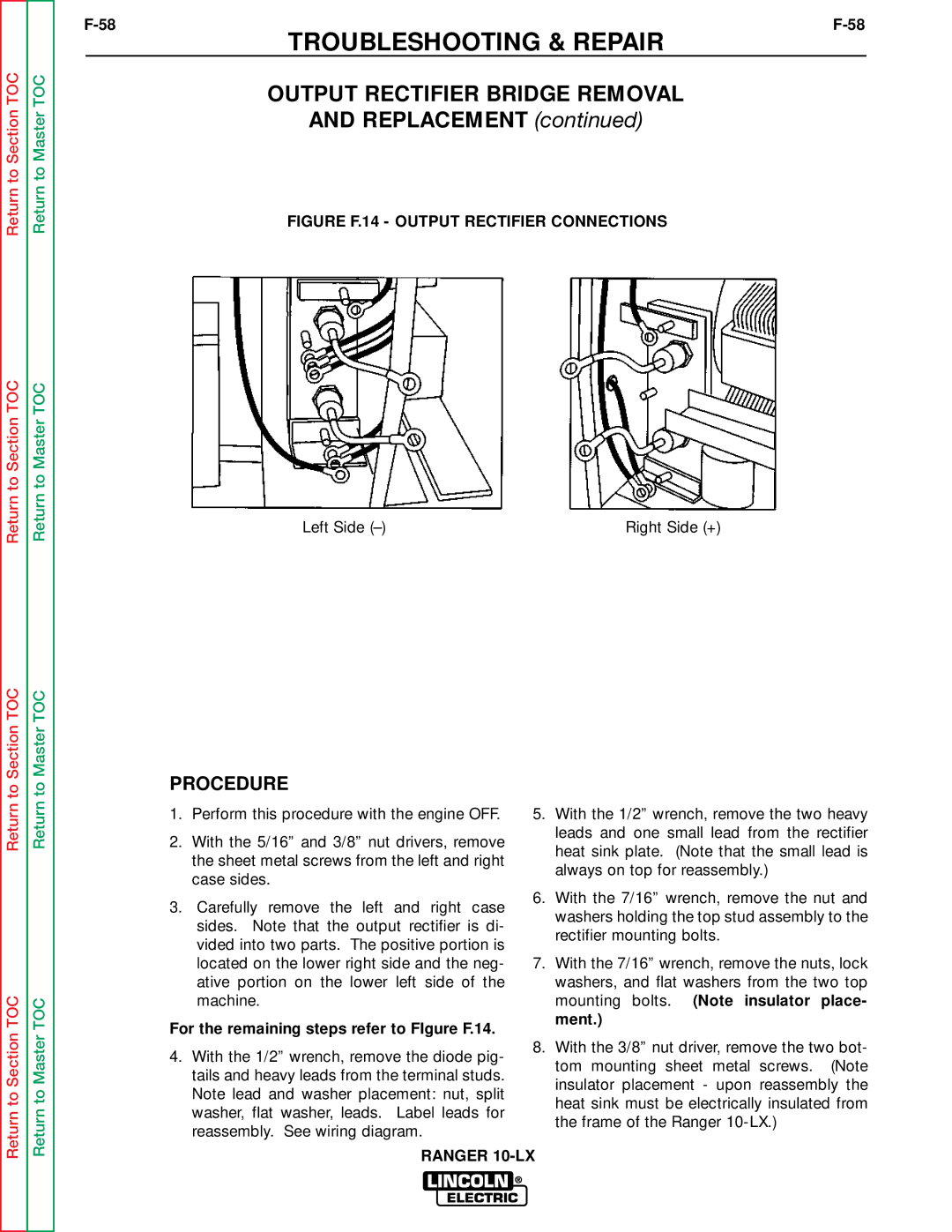
FIGURE F.14 - OUTPUT RECTIFIER CONNECTIONS
Left Side |
| Right Side (+) |
|
|
|
PROCEDURE
Return
Return to Section TOC
Return
Return to Master TOC
1.Perform this procedure with the engine OFF.
2.With the 5/16” and 3/8” nut drivers, remove the sheet metal screws from the left and right case sides.
3.Carefully remove the left and right case sides. Note that the output rectifier is di- vided into two parts. The positive portion is located on the lower right side and the neg- ative portion on the lower left side of the machine.
For the remaining steps refer to FIgure F.14.
4.With the 1/2” wrench, remove the diode pig- tails and heavy leads from the terminal studs. Note lead and washer placement: nut, split washer, flat washer, leads. Label leads for reassembly. See wiring diagram.
5.With the 1/2” wrench, remove the two heavy leads and one small lead from the rectifier heat sink plate. (Note that the small lead is always on top for reassembly.)
6.With the 7/16” wrench, remove the nut and washers holding the top stud assembly to the rectifier mounting bolts.
7.With the 7/16” wrench, remove the nuts, lock washers, and flat washers from the two top mounting bolts. (Note insulator place- ment.)
8.With the 3/8” nut driver, remove the two bot- tom mounting sheet metal screws. (Note insulator placement - upon reassembly the heat sink must be electrically insulated from the frame of the Ranger
RANGER