Section TOC
Master TOC
THEORY OF OPERATION
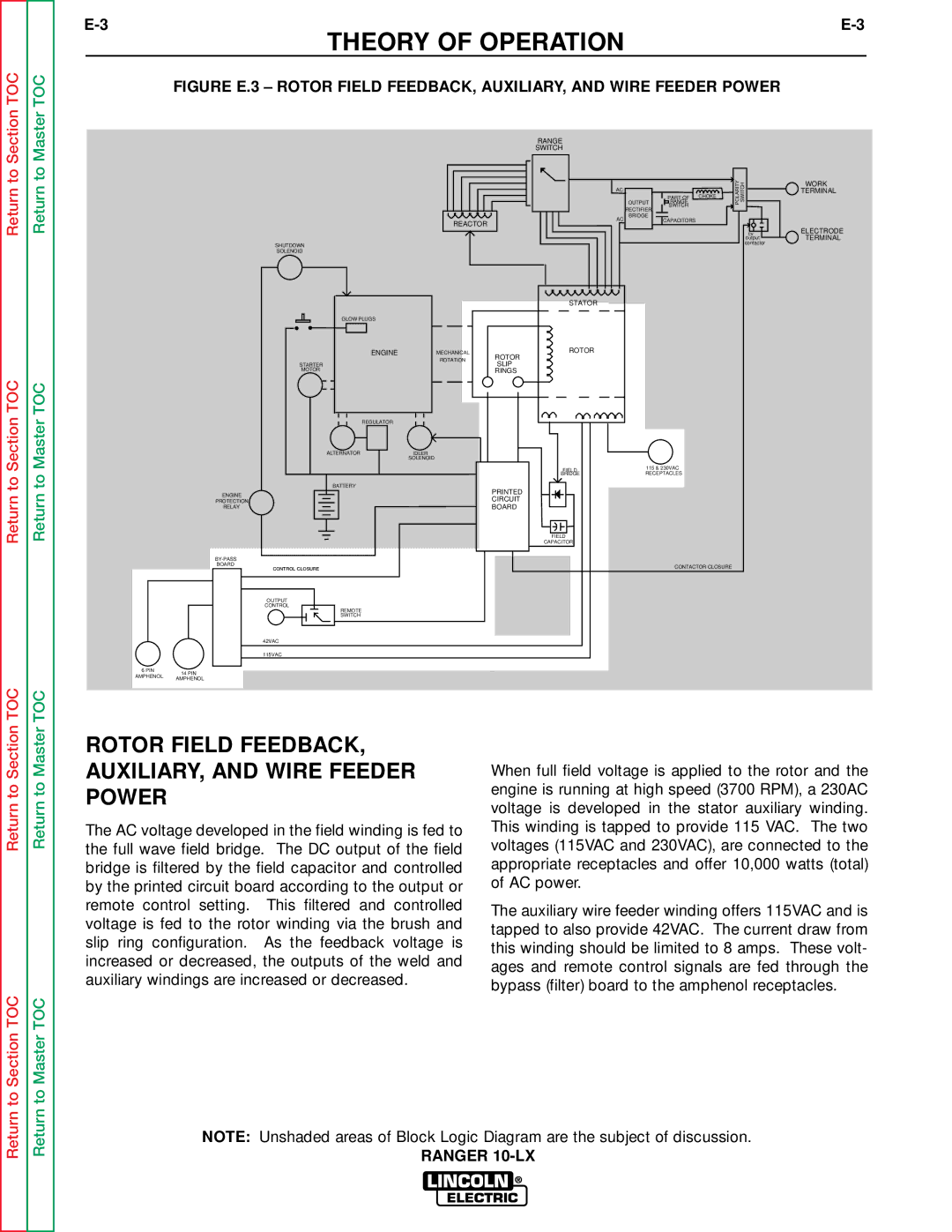
FIGURE E.3 – ROTOR FIELD FEEDBACK, AUXILIARY, AND WIRE FEEDER POWER
Return to
Return to Section TOC
Return to
Return to Master TOC
|
| RANGE |
|
|
|
|
|
| SWITCH |
|
|
|
|
|
| AC | OUTPUT | RANGE |
| POLARITY SWITCH |
|
|
|
| PART OF | CHOKE |
|
|
|
| RECTIFIER | SWITCH |
|
|
|
|
|
|
|
| |
|
| AC | BRIDGE | CAPACITORS |
|
|
| REACTOR |
|
|
| ||
|
|
|
|
|
| |
|
|
|
|
|
| cv |
|
|
|
|
|
| output |
SHUTDOWN |
|
|
|
|
| contactor |
|
|
|
|
|
| |
SOLENOID |
|
|
|
|
|
|
|
| STATOR |
|
|
|
|
GLOW PLUGS |
|
|
|
|
|
|
ENGINE | MECHANICAL | ROTOR |
|
|
|
|
ROTOR |
|
|
|
| ||
| ROTATION |
|
|
|
| |
STARTER | SLIP |
|
|
|
| |
|
|
|
|
| ||
MOTOR |
| RINGS |
|
|
|
|
REGULATOR |
|
|
|
|
|
|
ALTERNATOR | IDLER |
|
|
|
|
|
| SOLENOID |
|
|
|
|
|
|
| FIELD | 115 & 230VAC |
|
| |
|
| BRIDGE | RECEPTACLES |
|
| |
BATTERY |
| PRINTED |
|
|
|
|
ENGINE |
|
|
|
|
| |
| CIRCUIT |
|
|
|
| |
PROTECTION |
|
|
|
|
| |
RELAY |
| BOARD |
|
|
|
|
|
| FIELD |
|
|
|
|
|
| CAPACITOR |
|
|
|
|
|
|
|
|
|
| |
BOARD |
|
|
| CONTACTOR CLOSURE |
| |
CONTROL CLOSURE |
|
|
|
| ||
OUTPUT |
|
|
|
|
|
|
CONTROL |
|
|
|
|
|
|
REMOTE |
|
|
|
|
|
|
SWITCH |
|
|
|
|
|
|
42VAC |
|
|
|
|
|
|
115VAC |
|
|
|
|
|
|
6 PIN | 14 PIN | |
AMPHENOL | ||
AMPHENOL | ||
|
WORK
TERMINAL
ELECTRODE TERMINAL
Return to Section TOC
Return to Master TOC
ROTOR FIELD FEEDBACK, AUXILIARY, AND WIRE FEEDER POWER
The AC voltage developed in the field winding is fed to the full wave field bridge. The DC output of the field bridge is filtered by the field capacitor and controlled by the printed circuit board according to the output or remote control setting. This filtered and controlled voltage is fed to the rotor winding via the brush and slip ring configuration. As the feedback voltage is increased or decreased, the outputs of the weld and auxiliary windings are increased or decreased.
When full field voltage is applied to the rotor and the engine is running at high speed (3700 RPM), a 230AC voltage is developed in the stator auxiliary winding. This winding is tapped to provide 115 VAC. The two voltages (115VAC and 230VAC), are connected to the appropriate receptacles and offer 10,000 watts (total) of AC power.
The auxiliary wire feeder winding offers 115VAC and is tapped to also provide 42VAC. The current draw from this winding should be limited to 8 amps. These volt- ages and remote control signals are fed through the bypass (filter) board to the amphenol receptacles.
Return to Section TOC
Return to Master TOC
NOTE: Unshaded areas of Block Logic Diagram are the subject of discussion.
RANGER
