Section TOC
Master TOC
THEORY OF OPERATION
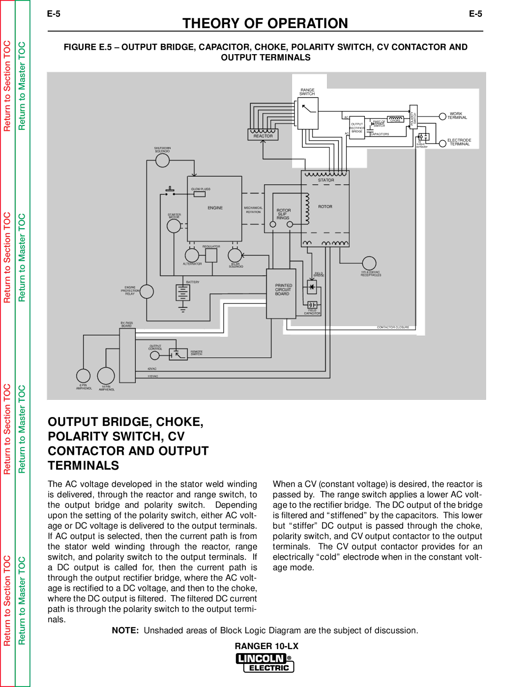
FIGURE E.5 – OUTPUT BRIDGE, CAPACITOR, CHOKE, POLARITY SWITCH, CV CONTACTOR AND
OUTPUT TERMINALS
|
| RANGE |
|
|
|
|
|
| SWITCH |
|
|
|
|
|
| AC |
|
|
| POLARITY SWITCH |
|
|
|
| PART OF | CHOKE | |
|
|
| OUTPUT | RANGE |
| |
|
|
| RECTIFIER | SWITCH |
|
|
|
|
|
|
|
| |
|
| AC | BRIDGE | CAPACITORS |
|
|
| REACTOR |
|
|
| ||
|
|
|
|
|
| |
|
|
|
|
|
| cv |
|
|
|
|
|
| output |
SHUTDOWN |
|
|
|
|
| contactor |
|
|
|
|
|
| |
SOLENOID |
|
|
|
|
|
|
|
| STATOR |
|
|
|
|
GLOW PLUGS |
|
|
|
|
|
|
ENGINE | MECHANICAL | ROTOR |
|
|
|
|
ROTOR |
|
|
|
| ||
| ROTATION |
|
|
|
| |
STARTER | SLIP |
|
|
|
| |
|
|
|
|
| ||
MOTOR |
| RINGS |
|
|
|
|
REGULATOR |
|
|
|
|
|
|
ALTERNATOR | IDLER |
|
|
|
|
|
| SOLENOID |
|
|
|
|
|
|
| FIELD | 115 & 230VAC |
|
| |
|
| BRIDGE | RECEPTACLES |
|
| |
BATTERY |
| PRINTED |
|
|
|
|
ENGINE |
|
|
|
|
| |
| CIRCUIT |
|
|
|
| |
PROTECTION |
|
|
|
|
| |
RELAY |
| BOARD |
|
|
|
|
|
| FIELD |
|
|
|
|
|
| CAPACITOR |
|
|
|
|
|
|
|
|
|
| |
BOARD |
|
|
| CONTACTOR CLOSURE |
| |
|
|
|
|
| ||
OUTPUT |
|
|
|
|
|
|
CONTROL |
|
|
|
|
|
|
REMOTE |
|
|
|
|
|
|
SWITCH |
|
|
|
|
|
|
42VAC |
|
|
|
|
|
|
115VAC |
|
|
|
|
|
|
6 PIN | 14 PIN | |
AMPHENOL | ||
AMPHENOL | ||
|
WORK
TERMINAL
ELECTRODE TERMINAL
Return to Master
OUTPUT BRIDGE, CHOKE, POLARITY SWITCH, CV CONTACTOR AND OUTPUT TERMINALS
to Section TOC
to Master TOC
The AC voltage developed in the stator weld winding is delivered, through the reactor and range switch, to the output bridge and polarity switch. Depending upon the setting of the polarity switch, either AC volt- age or DC voltage is delivered to the output terminals. If AC output is selected, then the current path is from the stator weld winding through the reactor, range switch, and polarity switch to the output terminals. If a DC output is called for, then the current path is through the output rectifier bridge, where the AC volt- age is rectified to a DC voltage, and then to the choke, where the DC output is filtered. The filtered DC current path is through the polarity switch to the output termi- nals.
When a CV (constant voltage) is desired, the reactor is passed by. The range switch applies a lower AC volt- age to the rectifier bridge. The DC output of the bridge is filtered and “stiffened” by the capacitors. This lower but “stiffer” DC output is passed through the choke, polarity switch, and CV output contactor to the output terminals. The CV output contactor provides for an electrically “cold” electrode when in the constant volt- age mode.
Return
Return
NOTE: Unshaded areas of Block Logic Diagram are the subject of discussion.
RANGER