TOC
TOC
THEORY OF OPERATION
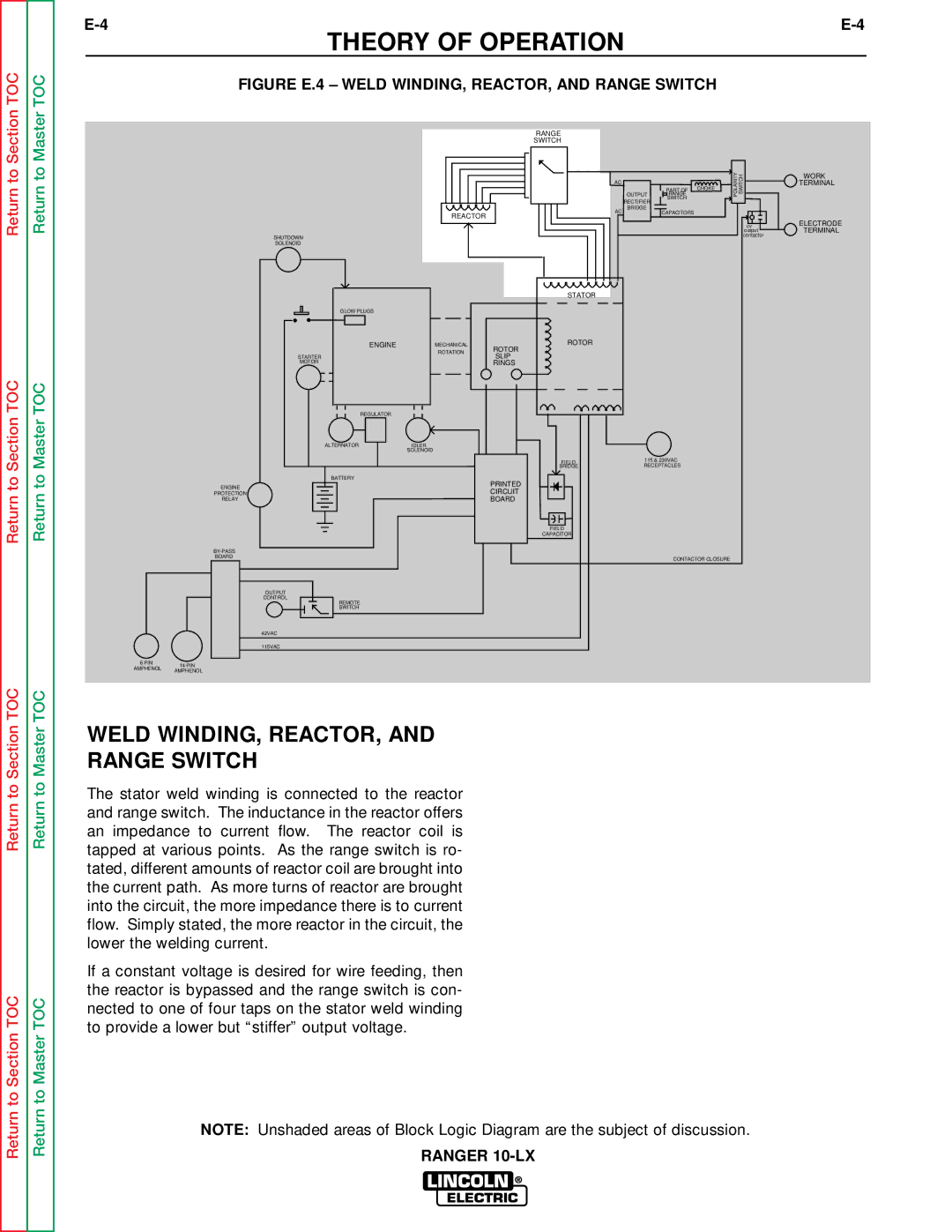
FIGURE E.4 – WELD WINDING, REACTOR, AND RANGE SWITCH
Return to Section
Return to Section TOC
Return to Master
Return to Master TOC
|
| RANGE |
|
|
|
|
|
| SWITCH |
|
|
|
|
|
| AC | OUTPUT | RANGE |
| POLARITY SWITCH |
|
|
|
| PART OF | CHOKE |
|
|
|
| RECTIFIER | SWITCH |
|
|
|
|
|
|
|
| |
|
| AC | BRIDGE | CAPACITORS |
|
|
| REACTOR |
|
|
| ||
|
|
|
|
|
| |
|
|
|
|
|
| cv |
|
|
|
|
|
| output |
SHUTDOWN |
|
|
|
|
| contactor |
|
|
|
|
|
| |
SOLENOID |
|
|
|
|
|
|
|
| STATOR |
|
|
|
|
GLOW PLUGS |
|
|
|
|
|
|
ENGINE | MECHANICAL | ROTOR |
|
|
|
|
ROTOR |
|
|
|
| ||
| ROTATION |
|
|
|
| |
STARTER | SLIP |
|
|
|
| |
|
|
|
|
| ||
MOTOR |
| RINGS |
|
|
|
|
REGULATOR |
|
|
|
|
|
|
ALTERNATOR | IDLER |
|
|
|
|
|
| SOLENOID |
|
|
|
|
|
|
| FIELD | 115 & 230VAC |
|
| |
|
| BRIDGE | RECEPTACLES |
|
| |
BATTERY |
| PRINTED |
|
|
|
|
ENGINE |
|
|
|
|
| |
| CIRCUIT |
|
|
|
| |
PROTECTION |
|
|
|
|
| |
RELAY |
| BOARD |
|
|
|
|
|
| FIELD |
|
|
|
|
|
| CAPACITOR |
|
|
|
|
|
|
|
|
|
| |
BOARD |
|
|
| CONTACTOR CLOSURE |
| |
|
|
|
|
| ||
OUTPUT |
|
|
|
|
|
|
CONTROL |
|
|
|
|
|
|
REMOTE |
|
|
|
|
|
|
SWITCH |
|
|
|
|
|
|
42VAC |
|
|
|
|
|
|
115VAC |
|
|
|
|
|
|
6 PIN | 14 PIN | |
AMPHENOL | ||
AMPHENOL | ||
|
WORK
TERMINAL
ELECTRODE TERMINAL
Return to Section TOC
Return to Section TOC
Return to Master TOC
Return to Master TOC
WELD WINDING, REACTOR, AND
RANGE SWITCH
The stator weld winding is connected to the reactor and range switch. The inductance in the reactor offers an impedance to current flow. The reactor coil is tapped at various points. As the range switch is ro- tated, different amounts of reactor coil are brought into the current path. As more turns of reactor are brought into the circuit, the more impedance there is to current flow. Simply stated, the more reactor in the circuit, the lower the welding current.
If a constant voltage is desired for wire feeding, then the reactor is bypassed and the range switch is con- nected to one of four taps on the stator weld winding to provide a lower but “stiffer” output voltage.
NOTE: Unshaded areas of Block Logic Diagram are the subject of discussion.
RANGER