Operation Procedure
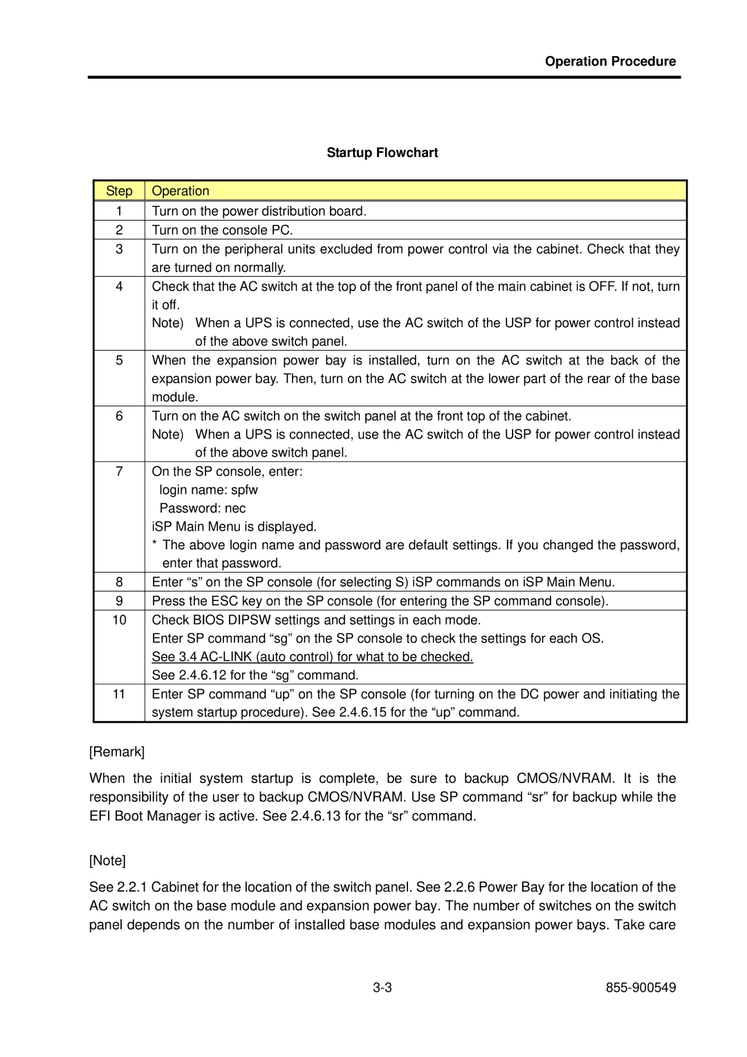
| Startup Flowchart |
|
|
Step | Operation |
1 | Turn on the power distribution board. |
2 | Turn on the console PC. |
3 | Turn on the peripheral units excluded from power control via the cabinet. Check that they |
| are turned on normally. |
4 | Check that the AC switch at the top of the front panel of the main cabinet is OFF. If not, turn |
| it off. |
| Note) When a UPS is connected, use the AC switch of the USP for power control instead |
| of the above switch panel. |
5 | When the expansion power bay is installed, turn on the AC switch at the back of the |
| expansion power bay. Then, turn on the AC switch at the lower part of the rear of the base |
| module. |
6 | Turn on the AC switch on the switch panel at the front top of the cabinet. |
| Note) When a UPS is connected, use the AC switch of the USP for power control instead |
| of the above switch panel. |
7 | On the SP console, enter: |
| login name: spfw |
| Password: nec |
| iSP Main Menu is displayed. |
| * The above login name and password are default settings. If you changed the password, |
| enter that password. |
8 | Enter “s” on the SP console (for selecting S) iSP commands on iSP Main Menu. |
9 | Press the ESC key on the SP console (for entering the SP command console). |
10 | Check BIOS DIPSW settings and settings in each mode. |
| Enter SP command “sg” on the SP console to check the settings for each OS. |
| See 3.4 |
| See 2.4.6.12 for the “sg” command. |
11 | Enter SP command “up” on the SP console (for turning on the DC power and initiating the |
| system startup procedure). See 2.4.6.15 for the “up” command. |
[Remark]
When the initial system startup is complete, be sure to backup CMOS/NVRAM. It is the responsibility of the user to backup CMOS/NVRAM. Use SP command “sr” for backup while the EFI Boot Manager is active. See 2.4.6.13 for the “sr” command.
[Note]
See 2.2.1 Cabinet for the location of the switch panel. See 2.2.6 Power Bay for the location of the AC switch on the base module and expansion power bay. The number of switches on the switch panel depends on the number of installed base modules and expansion power bays. Take care