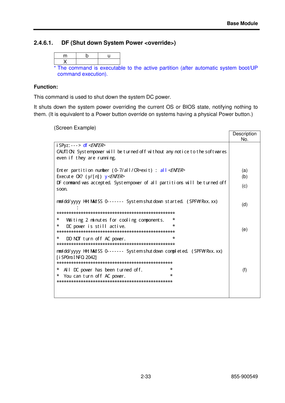
855-900549-A Rev NX7700i/5020M-16 Operation Manual
NEC Corporation
Disposing
used NEC
In the European Union
Outside the European
Safety Precautions
Handling of the lithium battery
Do not touch the internal components of the equipment
Do not insert foreign materials into the equipment
Failure processing
Disposing/collecting/recycling the equipment
Handling of the laser product
18kg
CAUTIONUse Copper
Conductors only ATTENTIONNutilisez que les conducteurs de cuivre
ATTENTIONMACHINE a FORT COURANT de FUITE
矢印を上に向けて取り付けること。
CAUTIONDisconnect input power before removing this cover
注※意:カバーを開ける前に入力電源分電盤切断のこと。
ATTENTIONCouper lalimentation electrique avant de demonter ce capot
注※意:保守時は安定板を引き出すこと。
保守者の方へ
警告 WARNING
保守者の方へ
警告 WARNING
243-304367-GRP
MARKINGS
243-306629-GRP
MARKINGS
Preface
Rev. 1, May
Contents
Cleaning Schedule
Preventing Accidental Erasure of Data
Life of Data Cartridge Tape for the DAT Unit
System Startup
Digital Audio Tape
Chapter 1 NX7700i/5020M-16 System Overview
Figure. External Views of the Cabinet
1.1. Configuration and Specifications of the Base Module
POWER BAY
Figure. Layout of Parts in the Base Module
NX7700i/5020M-16 System Overview
I/O MODULE
Table. Base Module Specifications
Table. Base Module Specifications Cont’d
NX7700i/5020M-16 System Overview
Main Cabinet
545Kg
1.2. Expandability
1.2.1. Adding Processors
1.2.2. Expanding Memory Capacity
1.2.3. Adding Cells
Itanium2
Figure. System Configuration
NX7700i/5020M-16 System Overview
Chapter
Base Module
Figure. Doors of Cabinet
Base Module
2.1. Partition Function
Figure. Image of Partitions
2.2. Name and Function of Components 2.2.1. Cabinet Primary Cabinet
BASE MODULE
BASE MODULE
POWBAY#1
2.2.3 Expansion Power Bay
2.2.2 Base Module
2.2.4 Cell
2.2.5. I/O Module
2.2.6. Power Bay
Figure. Rear panel of iSP Installed in the Base Module
2.2.7. iSP
Base Module
2.2.8.1. Loading and Unloading Media
2.2.8. DVD-ROM Unit
Figure. Loading and Unloading DVD-ROM/CD-ROM
2.2.9. DAT Unit
2.2.9.1. Location of Index Labels
2.2.9.2. Notes on Index Labels
2.2.9.3. Preventing Accidental Erasure of Data
2.2.9.4. Cleaning the DAT Unit
2.2.9.5. Cleaning Schedule
2.2.9.6. Cleaning Medium for the DAT Unit
2.2.9.7. Life of Data Cartridge Tape for the DAT Unit
2.2.9.10. Loading and Unloading Digital Audio Tapes
2.2.9.9. Notes on the DAT Unit
Figure. DAT Units
AC SW P1
2.2.10. Notes on Installing the UPS
Figure. Jumper Connector for Installing the UPS
AC SW
CB1 P3
AC SW
AC SW
2.2.11. System LEDs
LED CARD
2.3. Consoles
2.3.1. SP Console
Figure. Console Connection Diagram
Base Module
2.4. Service Processor SP
2.4.1. Console Connection and Login
2.4.1.2. Accessible Console Functions
2.4.1.1. Type of Console Connections
2.4.1.3. Console Status and Login Authentication
Serial console inoperative Press ESC Choose Exit iSP login prompt
Login password required
CM command
Password required
2.4.1.4. Login and Main Menu
The “backup” indicator will not appear if no backup SP exists
Screen Example…BOOT FW
iSP BOOT MAIN MENU S iSP commands E Exit
Description
Possible Events including operator entries and System Responses
2.4.2. Note
Base Module
2.4.3. OS BIOS Console
CTRL+B
Possible Events including operator entries and System Responses
Description
Base Module
2.4.4. Virtual SOP
Virtual System Operator Panel
Possible Events including operator entries and System Responses
Description
Base Module
2.4.4.1. Details of Partition Status Display
Base Module
2.4.5. SP Command Console
OSBIOS serial console of partition#0 INITIALIZING
Base Module
CTRL+B
2.4.5.2. SP Command Prompt
2.4.5.1. SP Command Console Buffer
2.4.5.3. SP Message Header
2.4.5.4. SP Command List
The following tables contain SP command lists by category
System Control
Base Module
Figure. System Status Transitions and System Control Commands
Configuration
Normal mode other commands
Settings
Base Module
2.4.6. SP Command Reference
Function
2.4.6.1. DF Shut down System Power override
Base Module
Description
Base Module
2.4.6.2. DN Shut down System Power
Function
2.4.6.3. DP System Dump
DP command was accepted. Dump button interrupt will be generated soon
Function
Base Module
2.4.6.4. DT SP Data and Time
Always valid without regard to the current system status
Function
Base Module
2.4.6.5. EN Environmental Information
32Way For one or two AC power receiving systems
ISPF does not have two AC power receiving systems
Always valid without regard to the current system status
Base Module
c d e f
2-39
The following information will be missing for 8Way
Base Module
Base Module
2-41
Base Module
The numbers of PCI Bay cards are changed on 32Way/8Way and ISPF
tentative
tentative
Description
Base Module
2.4.6.6. FV Firmware Versions
Always valid without regard to the current system status
Function
iSPyz--- fv ENTER
2.4.6.7. HC Hardware Configuration
Function
Base Module
Base Module
This command is currently not supported
Base Module
Base Module
Base Module
arg1
Base Module
Base Module
This command is currently not supported
Base Module
arg1
arg2
This command is currently not supported
Base Module
Base Module
Base Module
Description of Status Indicator Strings
Base Module
iSPyz--- hc ENTER
Base Module
HC helpENTER
Base Module
b c d e
2-59
The SM size is shown for the ISPF
Base Module
1 LIN=x,y,z x Logical IOX number
z “S” if SCSI SPLIT Mode is selected, and “N” if it is deselected
For 32WayH
For 32WayB
Base Module
For 8Way
Base Module
For ISPF
For 32WayB, 8Way, or ISPF
MMXx2 and MMXx3 are only shown for 32WayB
Base Module
2-63
Base Module
TAG0e
TAG0o
CELL1
j j j
Base Module
2-65
2 Listed for the PCI Bay in which the Core Cards are installed
3 Listed for the PCI Bay in which the Core Cards are installed
Base Module
For 32Way, subsequently listed to the max. XBX Card number
Base Module
2-67
POWBAYs Main cabinet
Base Module
POWBAYs Expansion cabinet
For the 8Way/ISPF model, there are three DPSs in Power Bay
For the ISPF, Power Bay1 for dual AC systems is not configured
Base Module
2-69
Description
Base Module
2.4.6.8. HE Help
Always valid without regard to the current system status
Function
Base Module
2.4.6.9. ML Message Log
Always valid without regard to the current system status
Function
Base Module
Description
Base Module
2.4.6.10. PC Power Cycle
iSP0mINFO.2129 partition 0 handed off the control to BIOS
Function
pcENTER
2.4.6.11. RS Cold Reset System
Function
Base Module
rsENTER
2.4.6.12. SG SP/System Setting
Setting partition boot method and hot-plug permission
Always valid without regard to the current system status
Function
ISPF
Base Module
LAN/Serial
SP SNMP Configuration
SP default FTP Server Configuration
Base Module
Base Module
Description
sgENTER
bENTER
Base Module
2ENTER
ENTER
onENTER
Description
Base Module
Base Module
Description
Base Module
Description
Base Module
Base Module
Manager1 LAN0 IP
Description
Base Module
2.4.6.13. SR Save System CMOS/NvRAM
Function
Base Module
file path cmossave/cmos1.bin ENTER
Description DescriptionDescription No
2.4.6.14. UB Bring up BIOS
Function
Base Module
mm/dd/yyyy HHMMSS 0------- System initialization started. SPFWRxx.xx
2.4.6.15. UP Bring up System
This command is valid to inactive partitions DC Off
Function
Base Module
Chapter 3 Operation Procedure
3.1. System Startup 3.1.1. System Startup Procedure
Operation Procedure
See step 3 in next page Expansion power bay/Base module AC ON
See steps 7 to 11 in next page OS Boot
Start
Remark
Operation Procedure
3.1.2. SP Console Messages
Operation Procedure
Operation Procedure
2 Example of SP console screen during system startup
3.2. System Shutdown 3.2.1. System Shutdown Procedure
Operation Procedure
Operation Procedure
See step 6 in next page Turn off AC to expansion power bay/base
Start Shut down OS See step 1 in next page Turn off console PC
module See steps 7 and 8 in next page Turn off peripherals
See 2.2.1 Cabinet for the location of the switch panel. See 2.2.6 Power Bay for the location of the AC switch on the base module and expansion power bay. The number of switches on the switch panel depends on the number of installed base modules and expansion power bays. Take care of the association between these switches and base modules and expansion power bays during switch operation. The switches on the switch panel are used for immediate power shutdown for emergency purposes. When a switch on this panel is turned off, data may be destroyed
3.2.2. SP Console Messages
Operation Procedure
1 Example of DC power off display on SP console screen
3-10
3.3. Emergency System Shutdown with AC SW
3.4. AC-LINK Auto Control
Data may be destroyed when the AC switch is turned off during
Provide criteria for operating the AC switch and use the switch
Operation Procedure
1 SP console screen and operation during AC LINK setup
= Enable AC LINK and press
3-12
3.5. OS Boot
3.5.1. OS Boot with Boot Manager Before Installing the OS
Use the arrow keys to change settings
Use the OS console to operate the EFI Shell. Inputs from the
Use the arrow keys to change settings
Image of the OS Boot screen displayed by the EFI Boot Manager
SLES9
3.5.3. EFI Shell
3.5.4. EFI Shell Commands
EFI Shell Commands
Command
Operation Procedure
Description
Command
Operation Procedure
Description
3.5.5. OS Boot from EFI Shell
Operation Procedure
Boot the OS loader
fs0¥ cd os
fs0¥os ls
3.5.6. EFI Devices
Computing UID
Example
3.5.7. EFI Boot Option Maintenance
Boot Maintenance Menu Options
Operation Procedure
Option
Description
Image of the Boot from a File screen
3.5.7.1. Boot from a File
Operation Procedure
ディレクトリを選択して実行プログ
3.5.7.2. Add a Boot Option
登 録 で き ま
3.5.7.3. Add Boot Options
3.5.7.4. Change Boot Order
3.5.7.5. Manage BootNext Setting
3.5.7.6. Set Auto Boot Timeout
3.5.7.7. Setting the Network Boot
AcpiPNP0A03,0/Pci30/Mac00004C717743
Changing procedure 1 Activate the EFI Boot Manager
3.5.7.8. Changing BIOS Settings
EFI System Configuration Menu Processor Configuration
3.6. System Dump
Chapter 4 Troubleshooting
4.1. Troubleshooting
pressing the SHIFT key on the screen
Chapter 5 Notes on Handling
5.1. Transportation
5.2. DVD-ROM/CD-ROM
5.3. Digital Audio Tape
5.4. Cleaning
Figure 5-1 Cleaning Locations
5.5. Notes on Installation
Notes on Handling
Memo