Operation Procedure
3.5.7.8.Changing BIOS Settings
The BIOS settings may need to be changed using the EFI System Configuration Menu.
After changing the BIOS settings, save the change using SP command “sr.” For the “sr” command, see 2.4.6.13.
(1) System interrupt
Check the BIOS settings for the hardware components shown below before installing Windows 2003 Server. Part of the BIOS settings is required for operating Windows 2003 Server. Be sure to set the proper system interrupt for the OS to install.
Confirmation and setting:
Select EFI System Configuration Menu from the EFI Boot Manager.
↓
Select Boot Configuration.
↓
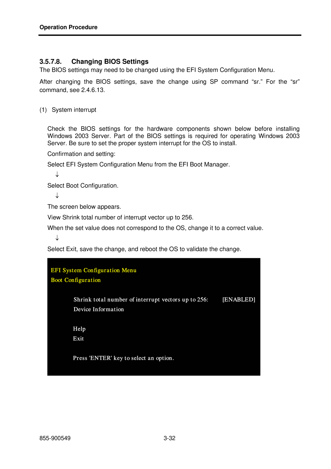
The screen below appears.
View Shrink total number of interrupt vector up to 256.
When the set value does not correspond to the OS, change it to a correct value.
↓
Select Exit, save the change, and reboot the OS to validate the change.
EFI System Configuration Menu
Boot Configuration
Shrink total number of interrupt vectors up to 256: | [ENABLED] |
Device Information |
|
Help |
|
Exit |
|
Press 'ENTER' key to select an option. |
|