Operation Procedure
|
| Shutdown Flowchart |
|
|
|
| |
Step | Operation |
| |
1 | Enter “shutdown |
| |
2 | Check that “Power down.” is displayed. |
| |
| For details of the shutdown command, refer to the OS manual. | ||
3 | When multiple partitions have been selected, repeat steps 1 and 2 for all partitions. | ||
4 | Check that the following is displayed on the SP console: | ||
| ************************************************** | ||
| * | All DC power has been turned off. | * |
| * | You can turn off AC power. | * |
| ************************************************** | ||
|
|
| |
5 | Check that the base module fan stops turning. |
| |
6 | Turn off the console management PC. |
| |
7 | Turn off the AC switch on the switch panel at the front top of the cabinet. | ||
| Note) | When a UPS is connected, use the AC switch of the USP for power control instead | |
|
| of the above switch panel. |
|
8 | When the expansion power bay is used, turn off the AC switch at the rear of the expansion | ||
| power bay. Then, turn off the AC switch at the lower part of the rear of the base module. | ||
9 | Turn off the peripheral units excluded from power control via the cabinet. | ||
10 | Turn off the distribution board. |
| |
[Note]
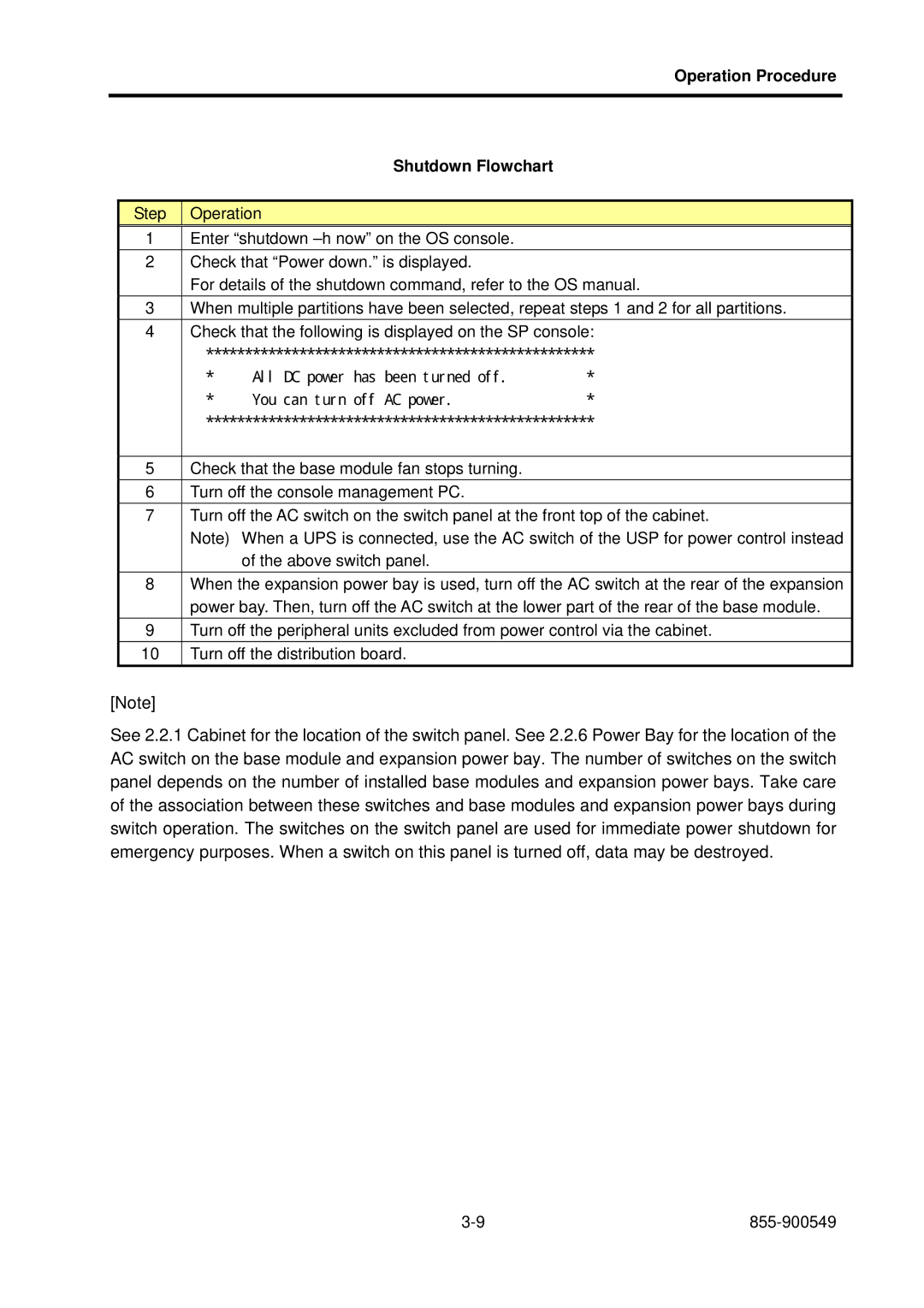
See 2.2.1 Cabinet for the location of the switch panel. See 2.2.6 Power Bay for the location of the AC switch on the base module and expansion power bay. The number of switches on the switch panel depends on the number of installed base modules and expansion power bays. Take care of the association between these switches and base modules and expansion power bays during switch operation. The switches on the switch panel are used for immediate power shutdown for emergency purposes. When a switch on this panel is turned off, data may be destroyed.
