2-16 Firmware User Guide
Multiple ATM Permanent Virtual Circuits
The Netopia Firmware Version 5.4 supports up to eight permanent virtual circuits.
Multiple ATM PVC overview
On
VCs are identified by a Virtual Path Identifier (VPI) and Virtual Channel Identifier (VCI). A VPI is an
■Circuits now support attributes in addition to their VPI and VCI values. When configuring a circuit, you can specify an optional circuit name of up to 14 characters. The circuit name is used only to identify the circuit for management purposes as a convenience to aid in selecting circuits from lists. The default circuit name is “Circuit <n>”, where <n> is some number between one and eight corresponding to the circuit’s position in the list of up to eight circuits.
■You can also individually enable or disable a circuit without deleting it. This is useful for temporarily removing a circuit without losing the configured attributes.
■In order to function, each circuit must be bound to a Connection Profile or to the Default Profile. Among other attributes, the profile binding specifies the IP addressing information for use on the circuit. Each circuit must be bound to a distinct Connection Profile. You cannot bind multiple circuits to the same Connection Profile.
Multiple ATM PVC configuration
ATM VPI/VCI Autodetection. You can bind multiple circuits to the same Connection Profile. Netopia Firmware Version 5.4 allows you to have a standard configuration that uses, for example, four VCs (0/35, 0/38, 8/35, 8/38) pointing to the same profile.
The unit will now automatically select the active VC on networks with a VPI/VCI of any of these four values without any custom configuration of the unit. You must, however, manually create these VCs and associate them with the profile you desire.
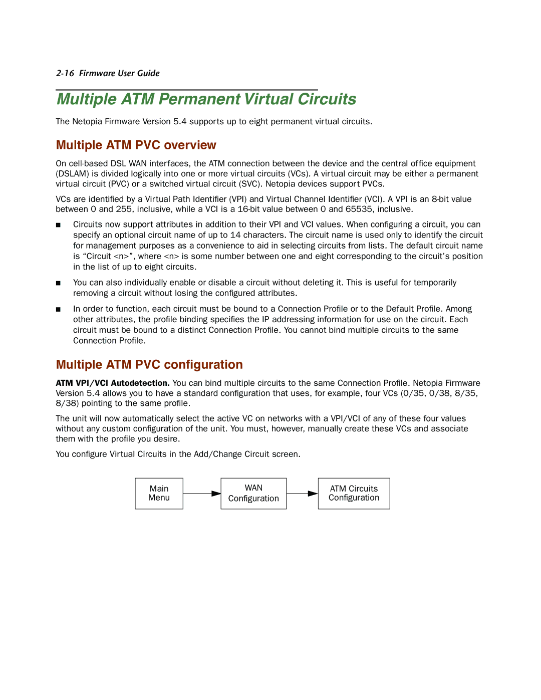
You configure Virtual Circuits in the Add/Change Circuit screen.
Main
Menu
WAN