22Chapter 3 Hardware Troubleshooting
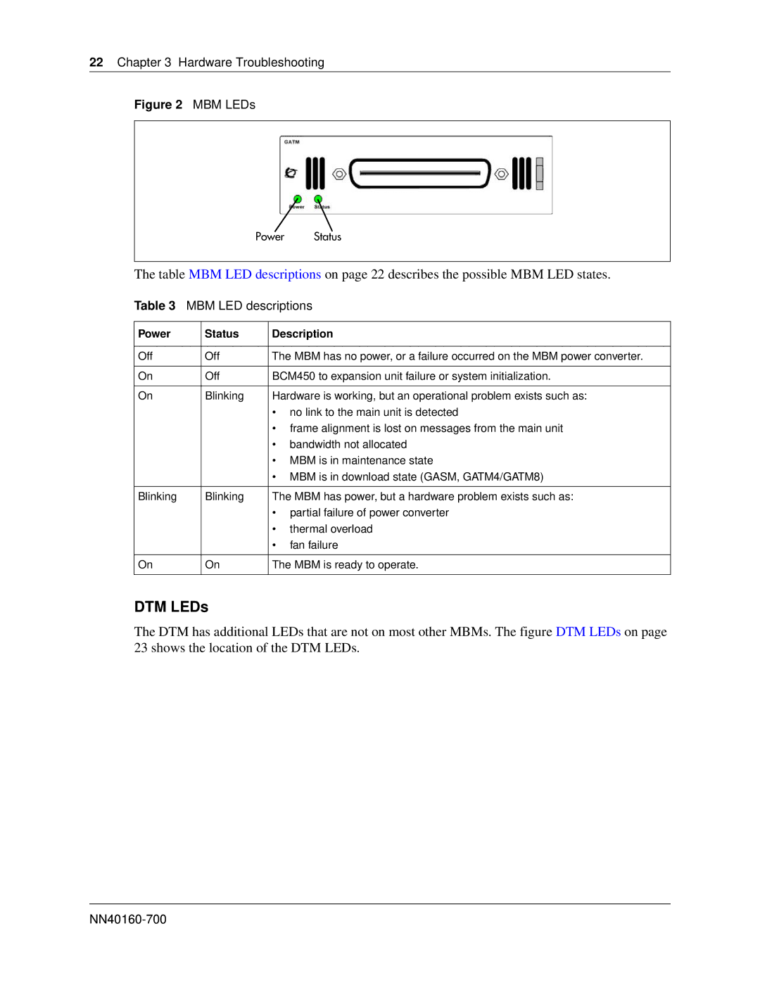
Figure 2 MBM LEDs
Power Status
The table MBM LED descriptions on page 22 describes the possible MBM LED states.
Table 3 MBM LED descriptions
Power | Status | Description | |
|
|
| |
Off | Off | The MBM has no power, or a failure occurred on the MBM power converter. | |
|
|
| |
On | Off | BCM450 to expansion unit failure or system initialization. | |
|
|
| |
On | Blinking | Hardware is working, but an operational problem exists such as: | |
|
| • no link to the main unit is detected | |
|
| • frame alignment is lost on messages from the main unit | |
|
| • | bandwidth not allocated |
|
| • MBM is in maintenance state | |
|
| • MBM is in download state (GASM, GATM4/GATM8) | |
|
|
| |
Blinking | Blinking | The MBM has power, but a hardware problem exists such as: | |
|
| • partial failure of power converter | |
|
| • | thermal overload |
|
| • | fan failure |
|
|
| |
On | On | The MBM is ready to operate. | |
|
|
|
|
DTM LEDs
The DTM has additional LEDs that are not on most other MBMs. The figure DTM LEDs on page 23 shows the location of the DTM LEDs.
