Chapter 3 Hardware Troubleshooting 23
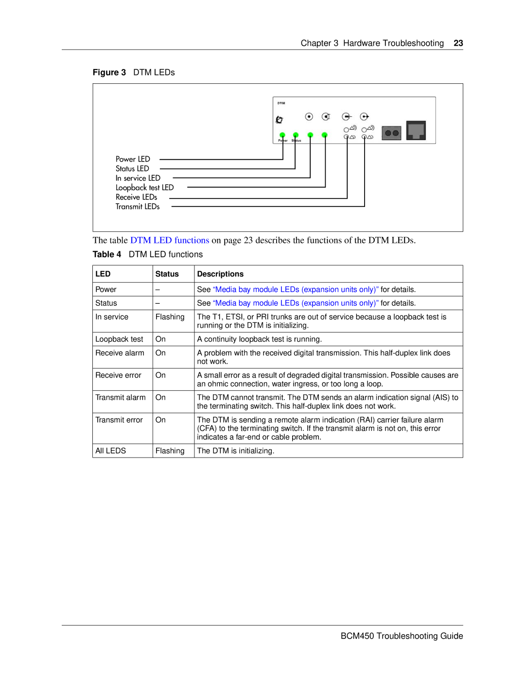
Figure 3 DTM LEDs
Power LED
Status LED
In service LED
Loopback test LED
Receive LEDs
Transmit LEDs
The table DTM LED functions on page 23 describes the functions of the DTM LEDs.
Table 4 DTM LED functions
LED | Status | Descriptions |
|
|
|
Power | – | See “Media bay module LEDs (expansion units only)” for details. |
|
|
|
Status | – | See “Media bay module LEDs (expansion units only)” for details. |
|
|
|
In service | Flashing | The T1, ETSI, or PRI trunks are out of service because a loopback test is |
|
| running or the DTM is initializing. |
|
|
|
Loopback test | On | A continuity loopback test is running. |
|
|
|
Receive alarm | On | A problem with the received digital transmission. This |
|
| not work. |
|
|
|
Receive error | On | A small error as a result of degraded digital transmission. Possible causes are |
|
| an ohmic connection, water ingress, or too long a loop. |
|
|
|
Transmit alarm | On | The DTM cannot transmit. The DTM sends an alarm indication signal (AIS) to |
|
| the terminating switch. This |
|
|
|
Transmit error | On | The DTM is sending a remote alarm indication (RAI) carrier failure alarm |
|
| (CFA) to the terminating switch. If the transmit alarm is not on, this error |
|
| indicates a |
|
|
|
All LEDS | Flashing | The DTM is initializing. |
|
|
|