20 Chapter 3 Hardware Troubleshooting
System status LEDs
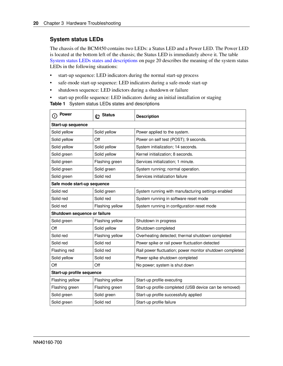
The chassis of the BCM450 contains two LEDs: a Status LED and a Power LED. The Power LED is located at the bottom left of the chassis; the Status LED is immediately above it. The table System status LEDs states and descriptions on page 20 describes the meaning of the system status LEDs in the following situations:
•
•
•shutdown sequence: LED indictors during a shutdown or failure
•
Table 1 System status LEDs states and descriptions
| Power | Status | Description |
| |||
|
|
| |
|
|
|
|
|
|
| |
|
|
|
|
Solid yellow | Solid yellow | Power applied to the system. | |
|
|
|
|
Solid yellow | Off | Power on self test (POST); 9 seconds. | |
|
|
|
|
Solid yellow | Solid yellow | System initialization; 14 seconds. | |
|
|
|
|
Solid green | Solid yellow | Kernel initialization; 8 seconds. | |
|
|
|
|
Solid green | Flashing green | Services initialization; 1 minute. | |
|
|
|
|
Solid green | Solid green | System running; normal operation. | |
|
|
|
|
Solid green | Solid red | Services initialization failure | |
|
|
|
|
Safe mode |
| ||
|
|
|
|
Solid red | Solid green | System running with manufacturing settings enabled | |
|
|
|
|
Solid red | Solid red | System running in software reset mode | |
|
|
|
|
Sold red | Flashing yellow | System running in configuration reset mode | |
|
|
|
|
Shutdown sequence or failure |
| ||
|
|
|
|
Solid green | Flashing yellow | Shutdown in progress | |
|
|
|
|
Off | Solid yellow | Shutdown completed | |
|
|
|
|
Solid red | Flashing yellow | Overheating detected; thermal shutdown completed | |
|
|
|
|
Solid red | Solid red | Power spike or rail power fluctuation detected | |
|
|
|
|
Flashing red | Solid red | Rail power fluctuation; power monitor shutdown completed | |
|
|
|
|
Solid yellow | Solid red | Power spike shutdown completed | |
|
|
|
|
Off | Off | No power; system is shut down | |
|
|
|
|
|
| ||
|
|
|
|
Flashing yellow | Flashing yellow | ||
|
|
|
|
Flashing green | Flashing green | ||
|
|
|
|
Solid green | Solid green | ||
|
|
|
|
Solid green | Solid red | ||
|
|
|
|
