i Mode selector [MODE] |
|
| |
Used to set a mode. |
| MODE | |
Set all the switches to OFF except |
| ||
|
| ||
when setting a mode. |
|
| |
ON1 2 3 4 5 6 7 8 9 10 | |||
• SW1 | |||
|
| ||
To initialize the IP address (IP=192.168.0.10) or other data already set.
• It takes about 10 seconds after SW1 is set to ON and the RESET button is pressed for the data to be initialized.
• After initializing, set SW1 back to OFF and press the RESET button again to restart.
• SW2
To return the HTML file, JPEG or other image data stored in the
Switch Positions
•It takes a few minutes after SW2 is set to ON and the RESET button is pressed for the data to be initialized.
•After initializing, set SW2 back to OFF and press the RESET button again to restart.
To return all data, including settings and home page, to the factory default settings, set both SW1 and SW2 to ON and press the RESET button.
•SW3, SW4, SW5, SW6, SW7, SW8, SW10 Keep these in the OFF position.
•SW9
Selects the
| SW1 | SW2 | SW3 | SW4 | SW5 | SW6 | SW7 | SW8 | SW9 | SW10 |
|
|
|
|
|
|
|
|
|
|
|
To operate | OFF | OFF | OFF | OFF | OFF | OFF | OFF | OFF | OFF | OFF |
|
|
|
|
|
|
|
|
|
|
|
To initialize | ON | ON | OFF | OFF | OFF | OFF | OFF | OFF | OFF | OFF |
|
|
|
|
|
|
|
|
|
|
|
oVideo input connectors [VIDEO IN 1/2/3/4] (BNC) Used to connect cameras.
To connect the control data cables of combination cameras (options)
!1RS-485 setup switches [RS485 SETUP]
Used when combination cameras with an
|
| SW1 | SW2 | SW3 | SW4 | ||||||||
|
|
|
|
|
|
|
|
|
|
|
|
|
|
Half Duplex (2 Lines)/termination ON |
|
|
| ON | ON | ON | ON | ||||||
|
|
|
|
|
|
|
|
|
|
|
|
|
|
Full Duplex (4 Lines)/termination ON |
|
|
| ON | OFF | OFF | ON | ||||||
|
|
|
|
|
|
|
| OFF | ON | ON |
| ||
Half Duplex (2 Lines)/termination OFF |
|
| ON | ||||||||||
|
|
|
|
|
|
|
| OFF | OFF | ON |
| ||
Full Duplex (4 Lines)/termination OFF |
|
| ON | ||||||||||
|
|
|
|
|
|
|
|
|
|
|
|
|
|
|
| SET UP |
|
|
|
|
|
| |||||
|
|
|
|
|
|
|
|
|
|
| |||
|
|
|
|
|
|
|
|
|
|
|
|
|
|
|
|
|
|
|
|
|
|
|
|
|
|
|
|
| ON1 2 3 4 |
|
|
|
| ||||||||
!2Alarm input/output port [ALARM]
To connect an external alarm unit. Input and output can be changed from the ADMINISTRATOR SETUP PAGE.
!3Video output connectors [VIDEO OUT 1/2/3/4] (BNC)
The video signal connected to VIDEO IN is looped through to this connector.
!4RS-232C port [RS-232C]
To connect a modem or CCTV equipment for control- ling the system.
!5Ethernet port [10BASE-T]
To connect a
!6DC power connector [DC 12V IN]
To connect the AC adapter (accessory).
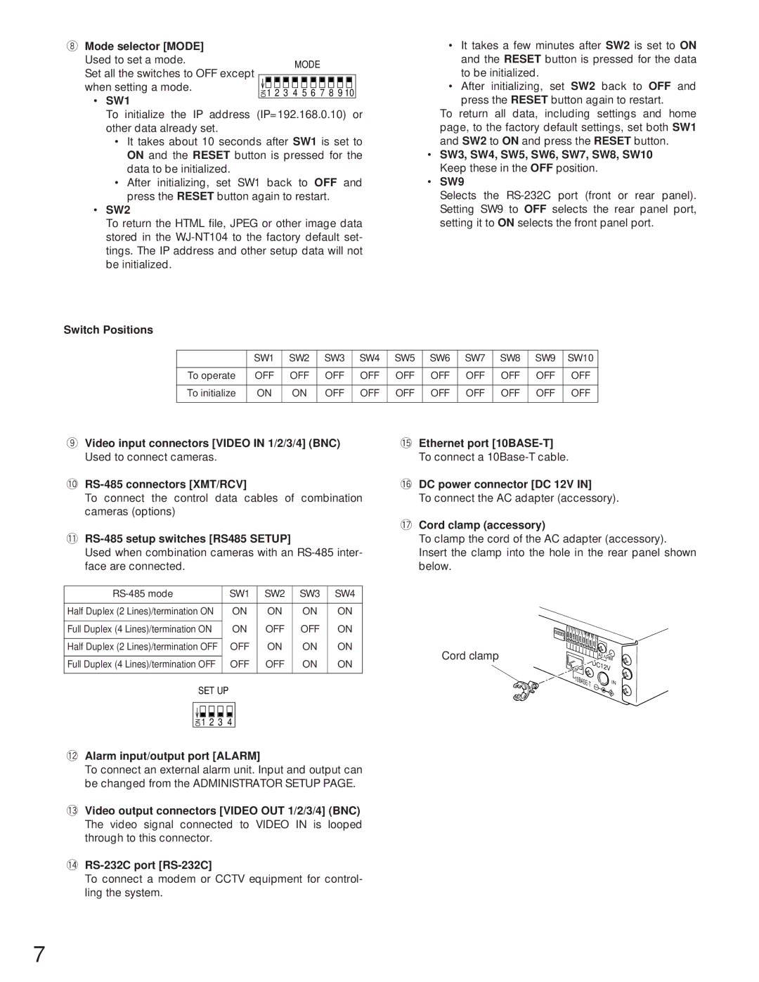
!7Cord clamp (accessory)
To clamp the cord of the AC adapter (accessory). Insert the clamp into the hole in the rear panel shown below.
Cord clamp | ALARM |
| DC12V |
IN |
7