■WJ-HD500 Digital Disk Recorder Control
It is enabled control of the
Also refer to the operating instructions for the disk recorder together.
●Connections
•Fixed input selection mode
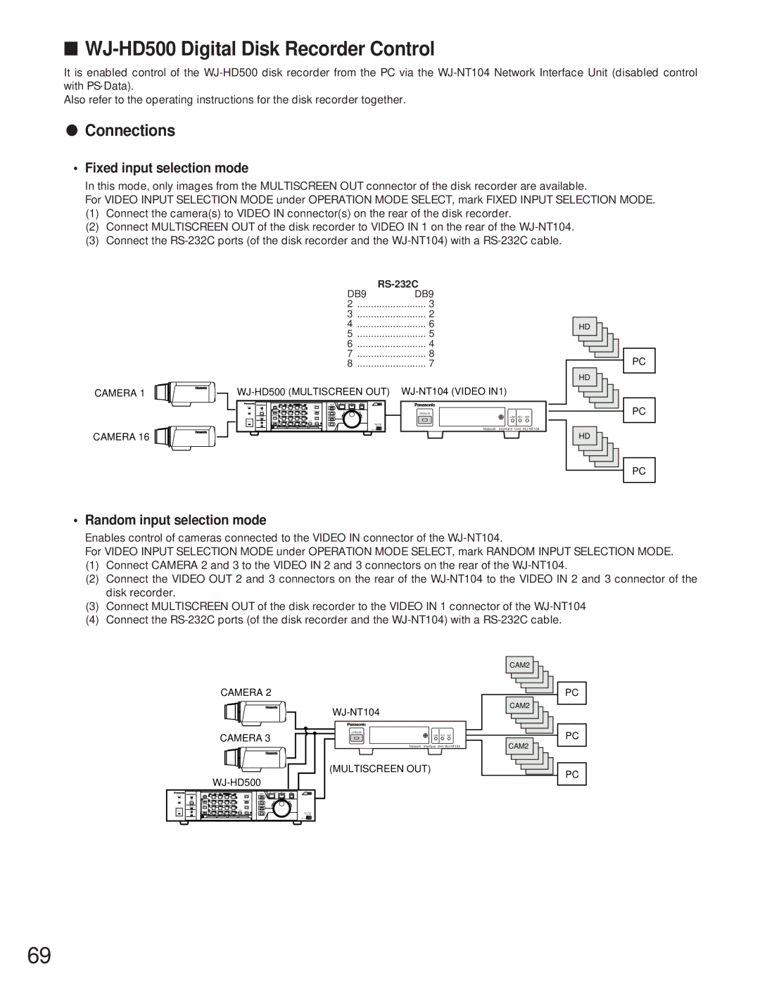
In this mode, only images from the MULTISCREEN OUT connector of the disk recorder are available.
For VIDEO INPUT SELECTION MODE under OPERATION MODE SELECT, mark FIXED INPUT SELECTION MODE.
(1)Connect the camera(s) to VIDEO IN connector(s) on the rear of the disk recorder.
(2)Connect MULTISCREEN OUT of the disk recorder to VIDEO IN 1 on the rear of the
(3)Connect the
|
| |
| DB9 | DB9 |
| 2 | 3 |
| 3 | 2 |
| 4 | 6 |
| 5 | 5 |
| 6 | 4 |
| 7 | 8 |
| 8 | 7 |
CAMERA 1 | ||
|
|
|
| FS 16 |
|
|
|
1 | 2 | 3 | 4 |
|
|
|
|
5 | 6 | 7 | 8 |
| OPERATE |
|
|
|
|
|
|
|
|
| |
9 | 10 | 11 | 12 |
|
| LINK RCV | XMT |
13 | 14 | 15 | 16 | Digital Disk |
|
|
|
|
|
|
| Recorder |
|
|
|
|
|
|
| Network | Interface Unit | ||
CAMERA 16 |
|
|
|
|
|
|
|
HD
HD
HD
PC
PC
PC
• Random input selection mode
Enables control of cameras connected to the VIDEO IN connector of the
For VIDEO INPUT SELECTION MODE under OPERATION MODE SELECT, mark RANDOM INPUT SELECTION MODE.
(1)Connect CAMERA 2 and 3 to the VIDEO IN 2 and 3 connectors on the rear of the
(2)Connect the VIDEO OUT 2 and 3 connectors on the rear of the
(3)Connect MULTISCREEN OUT of the disk recorder to the VIDEO IN 1 connector of the
(4)Connect the
CAMERA 2
CAMERA 3 | OPERATE |
LINK RCV XMT |
Network Interface Unit
(MULTISCREEN OUT)
|
| |||
|
|
|
| FS 16 |
1 | 2 | 3 | 4 |
|
5 | 6 | 7 | 8 |
|
9 | 10 | 11 | 12 |
|
13 | 14 | 15 | 16 | Digital Disk |
|
|
|
| Recorder |
|
|
|
| |
CAM2
CAM2
CAM2
PC
PC
PC
69
