Connections
•It is not possible to watch one TV programme and record another using this setup.
| 1 |
|
|
|
| SCART AV | |
Antenna/cable TV |
|
|
|
|
| connection | |
wall outlet |
|
|
|
|
|
| 2 |
|
|
| To antenna input |
|
|
| |
From SCART AV |
|
| VCR/Satellite receiver |
|
| Decoder | |
connector |
|
| /Cable box |
|
|
|
|
| 3 |
|
|
|
|
|
|
|
|
|
|
| AV2 (INPUT 1/ | ||
|
|
|
|
|
| DECODER) | |
ANTENNA R | AUDIO | L | VIDEO |
|
|
| DIGITAL |
IN |
|
|
|
|
|
| AUDIO OUT |
|
|
|
|
|
| ||
|
|
| INPUT 3 | AV 2 (INPUT 1/DECODER) |
|
| AC IN |
|
|
|
|
| ANTENNA(DIGITAL) HDMI OUT COAXIAL | ||
|
|
|
| IN | |||
|
|
|
| OUT | IN | ||
OUT |
|
| OUTPUT |
|
|
|
|
Y | PB |
| PR | AV 1 (RGB) – TV | CONTROL | 5 V | 30 mA |
COMPONENT VIDEO OUT |
|
|
| ||||
AV1 (RGB) - TV
4
To SCART AV
connector
TV
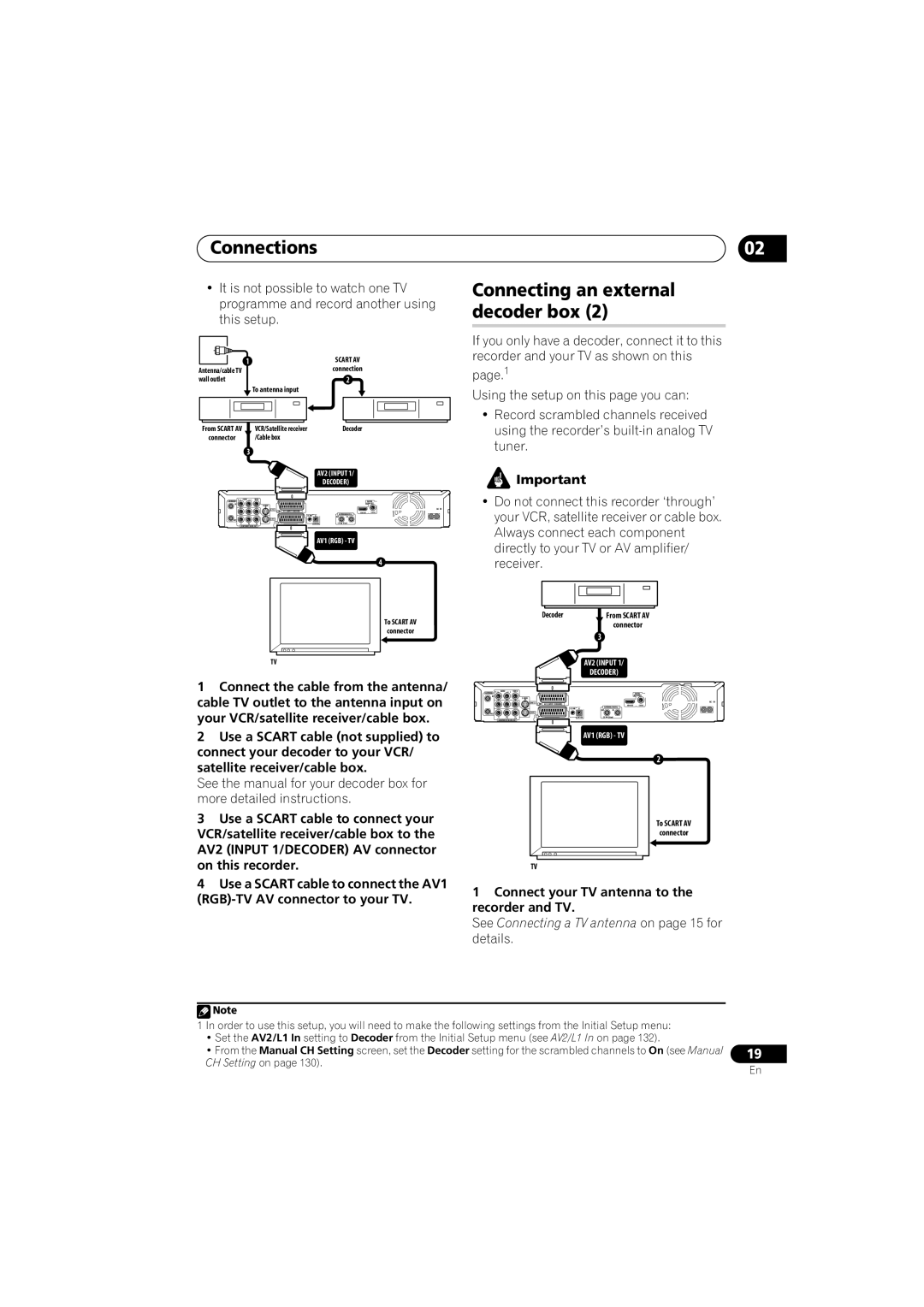
1Connect the cable from the antenna/ cable TV outlet to the antenna input on your VCR/satellite receiver/cable box.
2Use a SCART cable (not supplied) to connect your decoder to your VCR/ satellite receiver/cable box.
See the manual for your decoder box for more detailed instructions.
3Use a SCART cable to connect your VCR/satellite receiver/cable box to the AV2 (INPUT 1/DECODER) AV connector on this recorder.
4Use a SCART cable to connect the AV1
02
Connecting an external decoder box (2)
If you only have a decoder, connect it to this recorder and your TV as shown on this
page.1
Using the setup on this page you can:
•Record scrambled channels received using the recorder’s
![]() Important
Important
•Do not connect this recorder ‘through’ your VCR, satellite receiver or cable box. Always connect each component directly to your TV or AV amplifier/ receiver.
|
|
|
|
| Decoder |
|
| From SCART AV | |
|
|
|
|
|
|
|
| connector | |
|
|
|
|
|
|
| 3 |
|
|
|
|
|
|
|
|
| AV2 (INPUT 1/ |
| |
|
|
|
|
|
|
| DECODER) |
| |
ANTENNA | R | AUDIO | L VIDEO |
|
|
|
|
| DIGITAL |
IN |
|
|
|
|
|
|
| AUDIO OUT | |
|
|
|
| INPUT 3 | AV 2 (INPUT 1/DECODER) |
|
|
| AC IN |
|
|
|
|
|
| ANTENNA(DIGITAL) | HDMI OUT COAXIAL | ||
|
|
|
|
|
| OUT | IN |
| |
OUT |
|
|
| OUTPUT |
|
|
|
|
|
| Y | PB | PR |
| AV 1 (RGB) – TV | CONTROL | 5 V | 30 mA |
|
| COMPONENT VIDEO OUT |
|
|
|
|
| |||
AV1 (RGB) - TV
2
To SCART AV
connector
TV
1Connect your TV antenna to the recorder and TV.
See Connecting a TV antenna on page 15 for details.
![]() Note
Note
1 In order to use this setup, you will need to make the following settings from the Initial Setup menu:
•Set the AV2/L1 In setting to Decoder from the Initial Setup menu (see AV2/L1 In on page 132).
•From the Manual CH Setting screen, set the Decoder setting for the scrambled channels to On (see Manual CH Setting on page 130).
19
En