Supertrak
Trademarks
Copyright
Important data protection information
Recommendations
Radio Frequency Interference Statement
Page
Contents
Installing Drivers
SuperBuild Utility
Installing Drivers,
Management with WebPAM PRO
SuperBuild Utility,
107
Management with WebPAM PRO,
Managing Software Services,
Management with WebPAM PRO,
Management with WebPAM PRO,
Technology Background,
Troubleshooting
Support
Appendix a Partition and Format Appendix B Upgrades
287
Appendix D LED Backplane Connections
Xiv
About This Manual
Introduction
Hot-Swapping
Product Overview
XOR Microprocessor
Operating System Support
WebPAM PRO Management Software
Features Benefits
Key Features and Benefits
Browser Support
Advanced Hardware Design
Compatibility Features Benefits
Advanced Hardware Design Features Benefits
Compatibility
Specifications
Unpacking the SuperTrak Card
Installation
Page
Installing the SuperTrak Card
SuperTrak EX4650 card
SAS Ports Ch1-4
SuperTrak EX8654 card
SuperTrak EX16650 card
+ R G + + - +
Connecting SuperTrak to a VTrak Jbod Enclosure
Connecting SuperTrak to a SuperSwap Enclosure
Scenario 1 Virtual Enclosure Sgpio
SAS Connections and ID Numbers
Scenario 2 Virtual Enclosure Host PC
SuperTrak SAS Port Enclosure ID Range Drive ID Range
Scenario 5 SAS Expanders
Scenario 3 External Enclosures Daisy Chain
Scenario 4 External Enclosures Parallel
Level Number of Drives
Choosing the Physical Drives
Creating a Logical Drive
Installation
Page
Installation
Page
Installing onto Windows
Installing the CLI
License Agreement dialog box
Choose Destination Location dialog box
Ready to Install dialog box
Install Complete dialog box
Installing onto Linux
Introduction dialog box
License Agreement dialog box
Choose Install Folder dialog box
Pre-Installation Summary dialog box
Install Compete dialog box
Register On-line dialog box
Sh CLIInstaller...FreeBSD.bin -i silent
Installing the CLI onto FreeBSD
Sh CLIInstaller...VMware.bin -i silent
Installing the CLI onto VMware
Utility Server
Installing WebPAM PRO
Agent
Operating System Support
Browser Support
Internet Browser
Installing WebPAM PRO onto Windows
License Agreement dialog box
Setup Type dialog box
Custom Setup dialog box
Choose Destination Location dialog box
WebPAM PRO Server dialog box
Ready to Install dialog box
Install Complete dialog box
WebPAMPRO...Linux.bin file, then press Enter
Installing WebPAM PRO onto Linux
License Agreement dialog box
Choose Install Product dialog box
Choose Install Folder dialog box
SSL Security Options dialog box
Pre-Installation Summary dialog box
Install Compete dialog box
Register On-line dialog box
Logging in at the Host PC
Logging into WebPAM PRO
Logging in over the Network
Regular Connection
Https//192.168.10.2288443/promise
Login Screen
Click the Add Subsystem/Host tab
Setting up WebPAM PRO
Add Subsystem/Host tab
Installing Drivers
Click the Driver for Windows button
Driver Installation Media
Windows
Tar zxvf RH-306010003.tar.gz
Linux and FreeBSD
Load Driver
New OS Installation
Windows Server
Choose the Don’t search online option
Confirming Driver Installation
Existing System
Windows Vista
Existing System
Windows Server
Existing System
Windows XP
Existing System
Red Hat Linux Enterprise 4.4
Type sh ./install
Type mount -r /dev/fd0 /mnt/floppy
Type cd /mnt/floppy
Fedora Core
Fedora Core 7
SuSE Open 10.2, 10.3, 10.5
Type sh ./install Type cd umount /media/floppy
Type mount /dev/fd0 /media/floppy
Type cd /media/floppy
SuSE Sles 10, 10 SP1
Miracle Linux
Option 2. Device Node Does Not Exist
FreeBSD 6.1
Option 1. Device Node Exists
Existing System
VMware ESX Server 3.0.2
Esxcfg-boot -rg esxcfg-boot -b
Installing Drivers
Page
SuperBuild Utility
SuperTrak Bios
SuperTrak Bios screen
SuperTrak Bios screen, logical drive offline
SuperBuild Main Menu
Accessing the Main Menu
Selecting a Controller
Memory Type DDR2 Sdram
Viewing Controller Information
Viewing Physical Drive Information
Managing Physical Drives
Viewing Physical Drives
Managing Physical Drive Problems
Viewing Disk Array Information
Managing Disk Arrays
Viewing Disk Arrays
Creating a Disk Array
Deleting a Disk Array
Changing Disk Array Settings
Rebuilding a Disk Array
Viewing Logical Drive Information
Managing Logical Drives
Viewing Logical Drives
Creating a Logical Drive
Write Cache Policy Choose from Write Back or Write Through
Initializing a Logical Drive
Deleting a Logical Drive
Changing Logical Drive Settings
Selected logical drive is removed from the list
Viewing Spare Drives
Managing Spare Drives
Viewing Spare Drive Information
Creating a Spare Drive
Changing Spare Drive Settings
Deleting a Spare Drive
Viewing Background Activity
Viewing Nvram Events
Managing the Event Log
Viewing RAM Events
Clearing the Event Logs
Synchronizing Time with an Embedded Site
Setting the Time Zone
Working with Time Sync
Making the SAS Ready LED Setting
Using the Miscellaneous Menu
Making the Sgpio Backplane Setting
Working with the Buzzer
Enabling or Disabling the Buzzer
106
Management with WebPAM PRO
108
Management with WebPAM PRO
WebPAM PRO interface
Accessing the Interface
Using Tree View
Using the Header
WebPAM PRO Tree View
Using Management View
Viewing the Event Frame
Choosing a Display Language
Viewing the Storage Network
Saving the Event Frame
Deleting the Event Frame
Storage Network appears in Tree View
Logging out of WebPAM PRO
Viewing User Information
Making User Settings
Managing Users
Changing Your Own Password
Making Your Own User Settings
Changing a User’s Password
List of User Privileges
Creating a User
Deleting a User
119
Adding a Subsystem or Host
Working with Subsystem/Host Management
Viewing Subsystem/Host Information
Deleting a Subsystem or Host
In-Band versus Out-of-Band
Setting User Privilege
Changing Web Server Settings
Managing Software Services
Viewing Service Status
Restarting the Tomcat Server
Setting up Email Service
Windows
Linux
Sending a Test Email Message
Setting up Extended Smtp
Setting Event Frame Refresh Time
Changing CIM Server Settings
Changing CIM Client Settings
Managing the Host
Setting User Rights
Viewing Host Information
Refreshing the WebPAM PRO Screen
Viewing Subsystem Information
Managing the Subsystem
Clearing Statistical Data
Setting an Alias for the Subsystem
Updating the Firmware
Click the Clear Statistics link
Severity Definitions
Checking Subsystem Health
Viewing the Runtime Event Log
Viewing the Nvram Event Log
Saving the Runtime Event Log
Clearing the Runtime Event Log
Clearing the Nvram Event Log
Saving the Nvram Event Log
Viewing Current Background Activities
Making Background Activity Settings
Running Media Patrol
Running Background Activities
Scheduling an Activity
Running PDM
Viewing Scheduled Activities
136
Deleting a Scheduled Activity
Viewing System Configuration
138
Viewing Controller Information
Managing the Controller
Viewing Controllers Information
140
Viewing Controller Statistics
Making Controller Settings
Clearing an Orphan Watermark
Viewing Battery Information
Silencing the Buzzer
Making Buzzer Settings
Testing the Buzzer
Viewing Buzzer Information
Viewing Enclosure Information
Managing Enclosures
Virtual or Third Party Enclosures
Viewing a List of Physical Drives
Locating a Physical Drive
Sata Drives SAS Drives
Making Global Physical Drive Settings
Promise Enclosures
Viewing Physical Drive Statistics
Making Physical Drive Settings
Adjustable Items
Clearing Stale and PFA Conditions
Locating a Disk Array
151
Creating a Disk Array Automatic Configuration
Creating a Disk Array Express Configuration
154
Logical Drive Creation
Creating a Disk Array Advanced Configuration
Disk Array Creation
Summary
Disk Array Operational Status
Physical Drive Status
Making Disk Array Settings
159
160
Migrating a Disk Array
Rebuilding Manually
Rebuilding Automatically
Running PDM on a Disk Array
Running Media Patrol on a Disk Array
Preparing a Disk Array for Transport
Transitioning a Disk Array
165
Logical Drive Status
Viewing Information for All Logical Drives
Locating a Logical Drive
Logical Drive Synchronization
Viewing Logical Drive Statistics
Initialization
Viewing the Logical Drive Check Table
Running Redundancy Check
171
Viewing a List of Spare Drives
173
Deleting Spare Drive
Making Spare Drive Settings
Running Spare Check
Viewing a List of All Logical Drives
Working with the Logical Drive Summary
Viewing Individual Logical Drive Information
178
Navigate to the C\Program Files\WebPAMPRO\Agent\bin folder
Opening the CLI on Windows
Go to the /opt/Promise/WebPAMPRO/Agent/bin directory
Opening the CLI on Linux, FreeBSD, and VMware
Command Action
Table of Supported Commands
View redundancy check status and progress
This can be used in place of the help command or
About
List of Supported Commands
Array
Usage
Transport
Options
ID=
Decimal places. If not specified, all available capacity is
Examples
Battery
Bga
Bbm
Spare in the following condition
Buzz
Checktable
Config
193
Ctrl
Maximum amount of usable space
Command from host is supported
Enclosure
Date
Event
Export
Factorydefaults
Init
Logdrv
Migrate
Displayed
Pdm
Phydrv
Option. Defaults to be all if -d is not specified
Medium error threshold. If the threshold is reached,
Ptiflash
Port number
Rc -a start -l3 -n -p rc -a start -l3 Rc -a stop -l2
Spare
Spath
HBA
Stats
Subsys
Sync
Transit
Topology
Specifies the id of disk array which contains the revertible
Introduction to RAID
Technology Background
RAID 0 Striping interleaves data across multiple drives
RAID 0 Stripe
RAID 1 Mirrors identical data to two drives
RAID 1 Mirror
Enhanced Data Mirrors Physical Drives
RAID 1E Enhanced Mirror
RAID 5 stripes all drives with data and parity information
RAID 5 Block Striping with Distributed Parity
RAID 6 stripes all drives with data and dual parity
RAID 6 Block and Double Parity Stripe
Data Stripe Mirror Physical Drives
RAID 10 Mirror / Stripe
Component Minimum Maximum
RAID 50 Striped Distributed Parity
RAID 50 Axles
3,3,3
RAID 60 is a combination of RAID 6 and RAID
RAID 60 Striping of Double Parity
RAID 60 Axles
5,5 10,10 4,4,4 231
Advantages Disadvantages
Choosing a RAID Level
RAID 1E
234
High Read data transaction rate
Choosing Sector Size
Choosing Stripe Block Size
Logical Drive Size Sector Size
Choosing Cache Policy
TB Limitation
Write Cache Policy
Capacity Coercion
Read Cache Policy
Hot Spare Drives
Initialization
RAID Level Migration
Partition and Format the Logical Drive
Target Requirements
None
Add physical drives maximum
RAID 10 must have less than 16 physical drives
Physical drives maximum
PDM
Ranges of Disk Array Expansion
Current LD Size Maximum LD Sector Size Expansion Size
Delete and Recreate
PDM Triggers
Media Patrol
Predictive Data Migration PDM
Drive Failure and Automatic Rebuild
Transition
250
Manual Transition
Automatic Transition
252
Critical & Offline Logical Drives
When a Physical Drive Fails
254
Rebuild Operation
With a Hot Spare Drive
Without a Hot Spare Drive
256
LEDs
Problems Reported by SuperTrak
Buzzer
Global LED Display
Fault Activity Firmware Status
Direct LED Display
Logical Drive Status
Bios
260
What to Look For
Problems Reported in WebPAM PRO
Open WebPAM PRO
262
Finding the Failed Drive in SuperBuild
Physical Drive Management screen
Finding the Failed Drive in WebPAM PRO
Salvaging Physical Drives
Spare Drive Available
Rebuilding a Logical Drive
No Spare Drive Available
Manual Rebuild SuperBuild Utility
Manual Rebuild WebPAM PRO
Cache Battery Does Not Charge
Recovering from a Blank Screen
Pre-Installation Speed, Device Types, Capacity, Cabling
Frequently Asked Questions
Can I use Atapi devices on the SuperTrak EX Series?
Will Acpi work with HDDs on the SuperTrak EX Series?
How can I change the resources that the SuperTrak uses?
Drive Issues
Installation Issues Capacity, Booting
Aren’t the WebPAM PRO icons supposed to be animated?
Post-Installation
Why can’t I run WebPAM PRO in Konqueror?
Contacting Technical Support
Technical Support Services
United States
Netherlands
Taiwan
Germany
Italy
China
Disclaimer of other warranties
Limited Warranty
Your Responsibilities
Returning the Product For Repair
279
280
Appendix a Partition and Format
Click the Next button to start the Wizard
Appendix a Partition and Format
284
Downloading Bios and Firmware File
Updating SuperTrak Bios and Firmware
Installing the WebPAM PRO Update File
Downloading the WebPAM PRO Update File
Updating WebPAM PRO
Logging into WebPAM PRO
Appendix C Battery Backup Unit
Installing the BBU
BBU module connectors on EX4650. Other models are similar
290
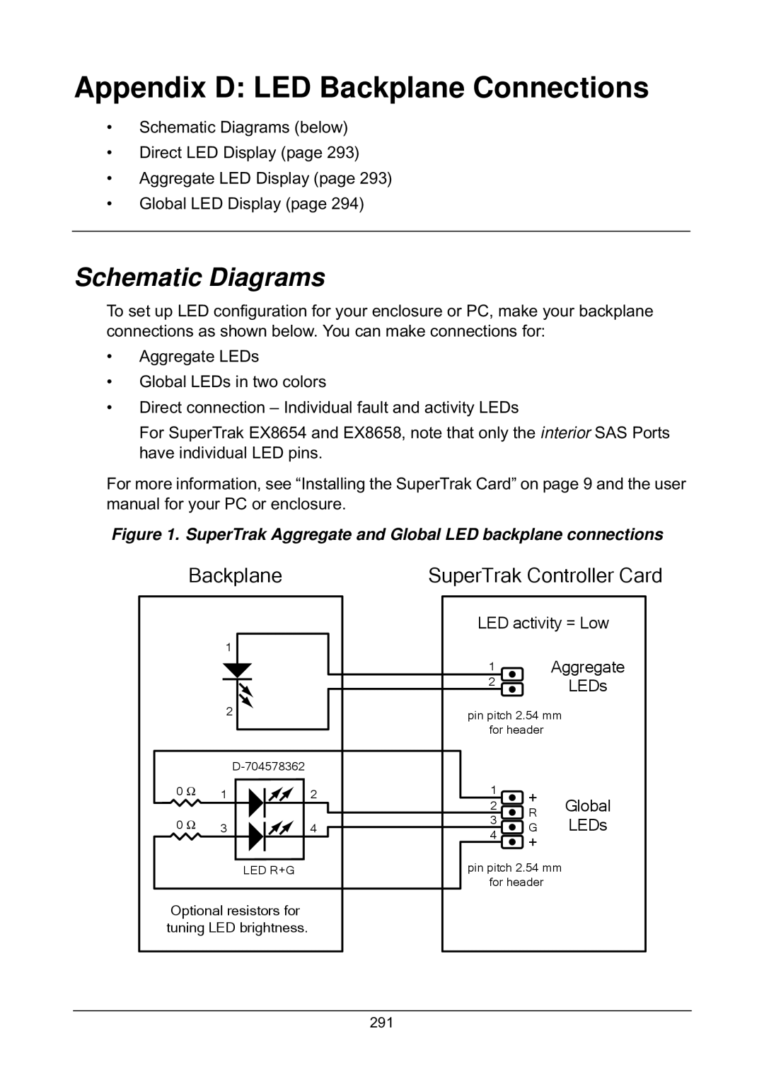
Appendix D LED Backplane Connections
Schematic Diagrams
Backplane
Storage Device Status
Direct LED Display
Aggregate LED Display
Global LED Display
Numerics
Index
Start 27
Jbod 14
107
Status 92, 93 Stripe size 21, 93, 156
Logical drive 94, 95, 156
Delete 99, 174 information List 97
Buzzer 104
VTrak Jbod 14, 16, 147, 151, 167
Info 166, 167