Simatic NET Profibus Networks Manual
05/2000 6GK1970-5CA20-0AA1 Release
Correct Usage
Safety Guidelines
Qualified Personnel
Trademarks
Symbols
Symbols
Contents
Passive Components for RS-485 Networks
Active Components for RS-485 Networks
Passive Components for Electrical Networks
Active Components for Wireless Networks
Testing Profibus
Passive Components for PROFIBUS-PA
Installing LAN Cables
Installing Network Components in Cubicles
Dimension Drawings
Glossary-1
Index Index-1
Page
Profibus Networks
Communication Systems
Distributed Systems
Overview of the Simatic NET System
Simatic NET
Industrial Ethernet/Fast Ethernet
AS-Interface
Basics of the Profibus Network
Attachable Systems
Transmission Media
Standards
Access Techniques
Token BUS/Master-Slave Method
Transmission Techniques
Active and Passive Nodes
Transmission Techniques According to EIA Standard RS-485
EIA Standard RS-485
Advantages
Restrictions
Properties of the RS-485 Transmission Technique
Transmission Techniques for Optical Components
Profibus User Organization Guideline
Integrated Optical Interfaces, OBT, OLM
Characteristics of the Optical Transmission Technique
OBT
Transmission Technique for Wireless Infrared Technology
Characteristics of the IEC 61158-2 Transmission Technique
Transmission Technique for PROFIBUS-PA
IEC 61158-2 Standard
Page
Topologies of Simatic NET Profibus Networks
LAN Cable
Topologies of RS-485 Networks
Transmission Rate
Node Attachment
Connecting Segments Using RS-485 Repeaters
Components for Transmission Rates up to 1.5 Mbps
Components for Transmission Rates up to 12 Mbps
Topologies of Optical Networks
Interfacing Electrical and Optical Networks/Components
Topology with Integrated Optical Interfaces
Topologies with OLMs
Profibus Optical Bus Terminal OBT
OLMs
Bus Topologies
Example of a Bus Topology with OLMs
Star Topologies with OLMs
Optical Channels
Redundant Optical Rings using OLMs
Monitoring FO Links
Mixed Structure
Topologies of Simatic NET Profibus Networks
Alternative Cabling Strategy
Combination of Integrated Optical Interfaces and OLMs
Point-to-Point Link
Topologies of Wireless Networks
Maximum Length of a Link
Infrared Link Module ILM
Point-to-Multipoint Link
Point-to-Point Link with Two Profibus ILMs
ILM Profibus
Bus and Star Topology
Field Device Power Supply via PROFIBUS-PA
Topologies with PROFIBUS-PA
SpliTConnect System
Expansion
Total Cable
Tap Line
Tap Line Lengths for DP/PA Couplers
Connectivity Devices 1 DP/DP Coupler
Uses
How the DP/DP Coupler Works
Parameter Assignment
Connecting to PROFIBUS-PA
DP/PA Bus Coupling
3 DP/PA Coupler
Uses of the DP/PA Coupler
Configuring the DP/PA Coupler
Properties of the DP/PA Coupler General
Properties of the DP/PA Coupler Ex
4 DP/PA Link
Definition
DP/PA Link
DP/PA Link
Properties
How the DP/PA Link Works
PA master
Rules
Connecting PROFIBUS-DP to RS-232C
18 DP/RS-232C Link for PROFIBUS-DP
How the DP/RS-232C Link Works
Device
Connecting with the DP/AS-Interface Link
20 DP/AS-Interface Link
DP/AS-Interface Link
How the DP/AS-Interface Link 65 Works
22 DP/AS-Interface Link
23 Example of a Configuration with DP/AS-Interface Link
How the DP/AS Interface Link 20 Works
Connecting PROFIBUS-DP to instabus EIB
24 DP/EIB Link
Building Automation
Industrial Automation
How the DP/EIB Link Works
S7-300 ET 200M
Configuring
Instabus EIB
Page
Configuring Networks
Configuring Electrical Networks
Profibus Networks
Parameters
Segments for Transmission Rates up to a Maximum of 500 Kbps
Transmission Rates up to a Maximum of 500 Kbps
Transmission Rate 1.5 Mbps
Segments for a Transmission Rate of 1.5 Mbps
Length of the Tap Lines
Node Attachments at 1.5 Mbps
Value Factors
Rules
Between two DTEs 10 m
Segments for Transmission Rates up to a Maximum of 12 Mbps
Transmission Rate up to a Maximum of 12 Mbps
Configuring Electrical Networks with RS-485 Repeaters
RS-485 Repeater
Configuring
Configuring Optical Networks
Configuration Parameters for Optical Networks
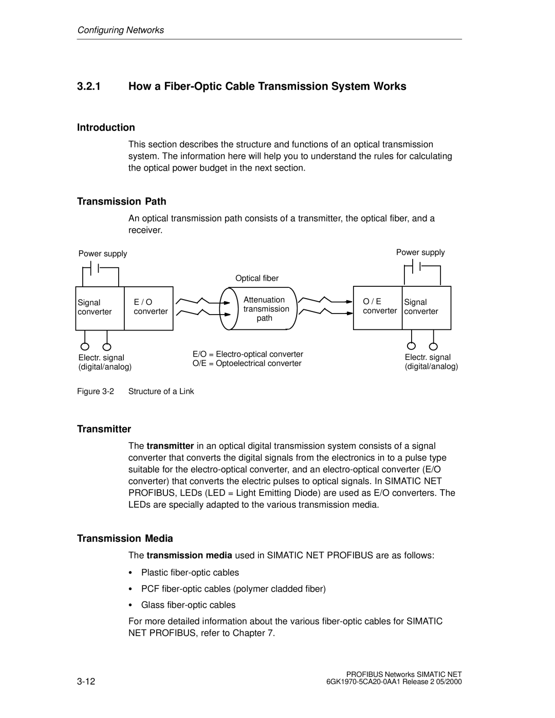
Transmission Path
How a Fiber-Optic Cable Transmission System Works
Introduction
Transmitter
Receiver
Attenuation
Optical Power Budget of a Fiber-Optic Transmission System
Optical Power Budget
Glass FO Cables
Power Budget
Plastic and PCF FO Cables
Splices
Link Power Margin
Work Sheet
For 1 Network =
Cable Lengths for Plastic and PCF FO Paths
Fiber-optic cable
Lengths between two Nodes in m
Mixing Plastic Fiber-Optic and PCF Fiber-Optic
Calculation Examples
AFOC =
Link power margin
Attenuation of the transmission path
Number * aSpl
10.0 dB
12 dB
Blank form for a power budget using OLMs
Transmission Delay Time
Configuring Optical Buses and Star Topologies with OLMs
Creating a System Overview
Setting the Profibus Properties
Properties Profibus Dialog
Entering the Cabling Configuration
Options Cables Tab
Checking the Bus Parameters
Bus Parameters Adapted to the System
Configuring Redundant Optical Rings with OLMs
Configuration of a Non-existent Node
Raising the Retry Value to at Least the Value
Checking and Adapting the Slot Time
Transmission Rate
Example of Configuring the Bus Parameters in Step
Structure of the Network Example
Transmission rate Minimum slot Time
Calculation of the Slot Time
Entering the Bus Parameters
Bus Parameters/User-Defined Dialog
Passive Components for RS-485 Networks
Simatic NET Profibus Cables
Profibus Cables
Overview
LAN Cables for Profibus
UV resistance
Sienopyr FR
Passive Components for RS-485 Networks
FC Standard Cable
FC Standard Cable 6XV1 830-0EH10
FC-FRNC Cable LAN cable with halogen-free outer sheath
LAN Cable with Halogen-free Outer Sheath 6XV1 830-0LH10
FC Food Cable
FC Food Cable 6XV1 830-0GH10
FC Robust Cable
FC Robust Cable 6XV1 830-0JH10
Profibus Flexible Cable
Profibus flexible cable 6XV1 830-0FH10
Properties
FC Underground Cable
FC Underground Cable 6GK1 830-3FH10
Filler
FC Trailing Cable
Trailing Cable 6XV1 830-3EH10
Properties
Example of Using the Profibus Trailing Cable in a Drag Chain
Segment Lengths
Passive Components for RS-485 Networks
Profibus Festoon Cable
Festoon Cable 6XV1 830-3GH10
10 Installation of the Profibus Festoon Cable Schematic
Passive Components for RS-485 Networks
Installation Guidelines
11 Use of the Profibus Cable for Festoons
SIENOPYR-FR Marine Cable
SIENOPYR-FR Marine Cable 6XV1830-0MH10
Inner sheath
Uses
FastConnect Bus Connector
FastConnect System
Functions
Designed for Industry
OLM
Technical Specifications
Order numbers 6ES7 0BA50-0XA0 0BB50-0XA0 6GK1 0FC00
Pinout of the Sub-D Male Connector
Disconnecting a Station
Bus Connector with PG Socket
Pin Signal Meaning Name
Passive Components for RS-485 Networks
Using the FastConnect Stripping Tool for Preparing FC Cables
OFF
Bus Connectors
Appearance
FMS/DP
Order 6ES7 972-0BA11-0XA0 6ES7 972-0BA40-0XA0 6GK1 Numbers
6ES7 972-0BB40-0XA0 0BA30-0XA0 500-0EA02
PG socket
Disconnecting a Station
Appearance 6ES7 972-0B.11
Siemens
Connecting Up the LAN Cable
First and last station on Further stations on the bus
Passive Components for RS-485 Networks
18 Bus Connector order number 6ES7 972-0BA30-0XA0
Appearance 6ES7 972-0BA30-0XA0
Cable guides Insulation displacement terminals
Connecting the LAN Cable to Bus Connector 6ES7 972-0B.40
Appearance 6ES7 972-0B.40
23 Connecting the LAN Cable to Bus Connector 6ES7 972-0B.40
Installing the Bus Connector with Axial Cable Outlet
Appearance 6GK1500-0EA02
Fitting the Bus Connector
Plugging the Bus Connector into the Module
Removing the Bus Connector
Possible disturbance of data traffic on the bus
Bus Terminals for RS-485 Networks Versions
Bus terminal RS-485 Bus terminal 12 M
Design and Functions of the RS-485 Bus Terminal
Bus Terminal RS-485
RXD/TXD-P
Additional PG Interface
28 RS-485 Bus Terminal with Additional PG Interface
Design and Functions of the 12M Bus Terminal
29 12M Bus Terminal BT12M
Bus terminal 12 M
30 Operator Controls
Restriction when using the 12M bus terminal at 500 Kbps
Termination
31 Drilling Diagram for the Bus Terminal
Mounting/Attaching the LAN Cables
Passive Components for RS-485 Networks
Passive Components for RS-485 Networks
33 Ways of Installing and Grounding the Bus Terminal
Grounding
Wall Mounting
Technical Data of the RS-485 Bus Terminal
Technical Data of the RS-485 Bus Terminal
Electromagnetic Compatibility
Technical Data of the 12M Bus Terminal
Technical Data of the 12M Bus Terminal
Climatic Conditions
Mechanical Conditions
Construction
Test Marks
All-round shielding of the LAN cable must be retained
Cable Connections Cable Connections to Network Components
Cable Connection without Bus Connection Elements
Avoid accidental shield contact with the environment
Keep to the permitted ambient conditions
Preassembled Connecting Cables 1 830-1T Connecting Cable
Function
Simatic NET 830-1T connecting cable
2 830-2 Connecting Cable
35 830-2 Connecting Cable
Simatic NET 830-2 connecting cable
Active Components for RS-485 Networks
RS-485 Repeater
What is an RS-485 Repeater?
Using the RS-485 Repeater 6ES7 972-0AA01-0XA0
Design of the RS-485 Repeater
Layout of the Repeater Function
Pinout of the Sub D Connector PG/OP Connector
Technical Specifications
Layout Pin no Signal name Meaning
Block Diagram
Block Diagram of the RS-485 Repeater
Possible Configurations with the RS-485 Repeater
Terminating Resistor On/Off
Off
Segment
Segments 1 and 2 Terminated
Segment 1 Terminated, Segment 2 Connected Through
Terminating resistor
Segments 1 and 2 Connected Through
Terminating resistor Bus segment 2 off
Installing and Uninstalling the RS-485 Repeater
Installation on an S7-300 Rail
Installing the RS-485 Repeater on an S7-300 Rail
Installation on a Standard Rail
Removing the Repeater from an S7-300 Rail
Removing the RS-485 from the Standard Rail
Ungrounded Operation of the RS-485 Repeater
Ungrounded Operation
Connecting the Power Supply
Connecting the Power Supply
Cable Type
Connecting the LAN Cable
Connecting the Profibus Cable
Order number
What is a Profibus Terminator?
Profibus Terminator
Design of the Profibus Terminator
Lists the technical data of the Profibus terminator
Standard cable 6XV1 830-0EH10
Page
Passive Components for PROFIBUS-PA
FC Process Cable
PVC outer sheath
SpliTConnect Tap
How the SpliTConnect Tap Works
Simatic NET
Produktinformation
Personnel qualification requirements
Insert the strand holder 6 onto the not stripped off strands
Grounding
Hinweis
SpliTConnect Coupler
SpliTConnect Terminator
Technische Daten /Technical Data
Passive Components for Electrical Networks
Fiber-Optic Cables
Fiber-Optic Cable FO
Plastic Fiber-Optic Cables
Plastic Fiber-Optic Cables
Properties of Fiber-Optic Cables
Properties of Fiber-Optic Cables
Plastic Fiber Optic, Duplex Cord
Plastic FO Cable, Duplex Cord 6XV1821-2AN50
Core Cladding Jacket buffer
Fiber-Optic Cables
Simatic NET Profibus Plastic Fiber Optic, Duplex Cord
Plastic Fiber-Optic, Standard Cables
Plastic FO Cable, Standard Cable 6XV1821-0A
Simatic NET Profibus plastic fiber-optic, standard cable
Standard lengths
PCF Fiber-Optic Cables
PCF FO Cable, Standard Cable 6XV1821-1B
PVC outer jacket Kevlar strain relief PCF fibers
Simatic NET Profibus PCF fiber-optic cable
Passive Components for Electrical Networks
Simatic NET Standard Fibers
Simple Configuration
Glass Fiber-Optic Cables
Guidelines for Laying Cables
Cable Type Fiber-Optic Standard Cable Indoor Fiber-Optic
TB3 Frnc or
Cable Type Fiber-Optic Indoor Fiber-Optic Standard Cable
Cable Type Flexible Fiber-Optic
Trailing Cable Duplex Fiber-Optic Marine Cable
13.3 ±
Fiber-Optic Standard Cable
Fiber-Optic Standard Cable
Indoor Fiber-Optic Cable
Indoor Fiber-Optic Cable
Flexible Fiber-Optic Trailing Cable
Flexible Fiber-Optic Trailing Cable
Uses
Passive Components for Electrical Networks
Sienopyr Duplex Fiber-Optic Marine Cable
Sienopyr Duplex Fiber-Optic Marine Cable 6XV1 830-0NH10
Ordering
Fiber Types
Special Cables
Special Cables
Cable Structures
Ordering
Fiber-Optic Connectors
Connectors for Plastic Fiber-Optic Cables
Requirements
Accessories
Order Numbers
Cable Lengths
Installing Plastic Fiber-Optic Cables
Instructions for Assembling Plastic Fiber-Optic Cables
Bfoc Connectors for OLMs
Connectors for Glass Fiber Cables
Bfoc Connectors for Glass Fiber-Optic Cables
Fitting Connectors On-Site
Preassembled Cables
Page
Active Components for Optical Networks
Optical Bus Terminal OBT
Optical Bus Terminal
Operating Instructions
6GK1 500-3AA00
Optical Link Module OLM
Design
Functions
Profibus OLM/P11
Page
Active Components for Wireless Networks
Infrared Link Module ILM
Ordering Data
Profibus ILM
Page
Testing Profibus
Hardware Test Device BT200 for PROFIBUS-DP Possible Uses
Area of Application
Logging Functions
Design
Figure A-1 Hardware Test Device BT200 for Profibus DP
Checking the Profibus Cable
Checking the Accessibility of Nodes
Functions
Checking the RS-485 Interface of a Slave
How the Unit Functions
Ordering Data
Testing FO Transmission Paths Necessity of a Final Test
Optical Power Source and Meter
Test Methods
Arrangement for Measuring Attenuation
Evaluating the Results of the Attenuation Measurements
Optical Time Domain Reflectometer Otdr
Figure A-3 Optical Time Domain Reflectometer Otdr
How an Otdr Functions
Figure A-4 How an Otdr Functions
Otdr Evaluation
Otdr provides the measurement results graphically
Checking the Optical Signal Quality with Profibus OLM
OLM/G12
Page
Page
Further Literature
Why Protect Your Automation System From Overvoltage?
Protecting LAN Cables from Lightning
Bus Cables within Buildings
LAN Cables between Buildings
Coarse Protection
PLC PLC
Instructions for Installing Coarse Protection
Instructions for Installing Fine Protection
Page
Page
Installing LAN Cables
Keep the Overall System Concept in Mind
LAN Cables in Automation Systems
LAN Cables as Important Plant Connections
Networking Simatic with Simatic NET
DC Power Supply
Electrical Safety
Power Supply Voltage
Protection from External Electrical Influences
Mechanical Protection of LAN Cables
Protection of Electrical and Optical LAN Cables
Mechanical Protection
Redundant LAN Cables
Do not kink or crimp the trailing and festoon cables
Install LAN cables separately
Electromagnetic Compatibility of LAN Cables
Measures to Counter Interference Voltages
Electromagnetic Compatibility EMC
Grounding
Installation and Grounding of Inactive Metal Parts
Using the Shields of Electrical LAN Cables
Cable Shields
Handling the Shield
When do potential differences occur?
Equipotential Bonding
When and why is equipotential bonding necessary?
How do you avoid potential differences?
Rules for Equipotential Bonding
Installing LAN Cables
Routing Electrical LAN Cables
Cable Categories and Clearances
How to Read the Table
Conditions
Clearance Table
Cables for Lay
Within closets
Outside closets
Cabling within Closets
Cabling within Buildings
Cabling outside Buildings
Fiber-optic cables should be given preference
EMC Rules for Electrical LAN Cables
Special Noise Suppression Measures
Connecting Switched Inductances to Suppressors
Power Supply for Programming Devices
Underground Cabling
Cabinet Lighting
Electromagnetic Compatibility of Fiber-Optic Cables
General
Temperatures
Pull Cables Using Cable Grips and Protect Connectors
Storage and Transportation
Torsion
Fitting Strain Relief
Pressure
Do not twist trailing cables and festooned cables
Installing other Cables
Avoid Loops
Attachments to Profibus Cables
Additional Instructions on Installing Fiber-Optic Cables
Attaching Profibus Fiber-Optic Cables
Page
Page
Installation Instructions for Simatic NET
Simatic NET
Personnel qualification requirements
Copyright Siemens AG All Rights Reserved
Page
Page
Setting the Cutting Depth of the Cable Knife
Page
Separating the Simatic NET Plastic Fiber Optic Duplex Cord
Removing the Buffer
Fitting Simplex Connectors
Connector must be towards the center
Simatic NET Profibus Plastic Fiber Optic, standard cable
Simatic NET Profibus Plastic Fiber Optic, duplex cord
Simatic NET Profibus Plastic Fiber Optic Stripping Tool Set
Other commercially available accessories
Plug adapter
Simatic NET
Personnel qualification requirements
Page
Setting the Cutting Depth of the Cable Knife
Foil working from the end of the cable
Separating the Simatic NET Plastic Fiber Optic Duplex Cord
Removing the Buffer
Crimping the Bfoc Connector
Grinding and Polishing Bfoc Connectors
Page
Simatic NET Profibus Plastic Fiber Optic Bfoc crimping tool
Simatic NET Profibus Plastic Fiber Optic Standard cable
Simatic NET Profibus Plastic Fiber Optic Duplex cord
Simatic NET Profibus Plastic Fiber Optic Bfoc polishing set
Other commercially available accessories
Simatic NET Profibus PCF Fiber Optic Standard Cable
Personnel qualification requirements
Simatic NET Profibus PCF Fiber Optic Standard Cable
Using the Pulling Loop
Marking Simatic NET Profibus PCF Fiber Optic Standard Cable
Simatic NET Profibus PCF Fiber Optic, standard cable
Assembled with 2 x 2 Bfoc connectors
For connecting OLM/P
Simatic NET Profibus PCF Fiber Optic cable
Installing Network Components Cubicles
IP Degrees of Protection
IEC 60529, EN
Degree of Protection
Code Contact and Solid Body Water Protection Number
Ventilation Openings
Outdoor Installation
Simatic NET Components
Heat Dissipation
Standards
Dimension Drawings
Dimension Drawings of the Bus Connectors
Figure F-2 Bus Connector to IP 20 6ES7 972-0BA30-0XA0
On OFF Siemens
Figure F-6 FastConnect Bus Connector 6GK1 500-0FC00
Dimension Drawings of the RS-485 Repeater
Figure F-7 RS-485 Repeater on Standard Rail 125
Dimension Drawing of the Profibus Terminator
Figure F-9 Profibus Terminator 40.3 44.5
Dimension Drawings of the RS-485 Bus Terminal
Figure F-10 RS-485 Bus Terminal on 15 mm high Standard Rail
Dimension Drawings of the BT12M Bus Terminal
Figure F-11 BT12M Bus Terminal on 15 mm high Standard Rail
Dimension Drawings of the Optical Bus Terminal OBT
Simatic NET
Dimension Drawings Infrared Link Module ILM
Sieme N S
Dimension Drawings Optical Link Module OLM
Dimension Drawings
Page
Operating Instructions ILM / OLM / OBT
Operating Instructions ILM / OLM / OBT
Simatic NET
Attenzione
Simatic NET Profibus ILM
General
Personnel qualification requirements
Installing the Profibus ILM
Modes and Settings
Installation and Startup
Signaling Contact Displays
Help With Problems During Operation
Product
Symbols
Introduction
Description of the Device
Siemens Profibus ILM
Transmission Rate
Topologies
Point-to-Point-Link
Point-to-Point Link with Two Profibus ILMs Slave
Infrared Link Modul ILM 6ZB530-3AC30-0BA1
Slave
Page
ILM
Point-to-Multipoint Link
Infrared transmission link 2 0.5 to 15 m
Signal Regeneration
Monitoring the Received Optical Level
Constant Light Monitoring
Monitoring the Optical Link
Monitoring the Optical Receive Activity
Monitoring the Optical Link with an Acknowledgment Pulse
Infrared Link Modul ILM 6ZB530-3AC30-0BA1
Modes and Settings
Setting the Terminating Resistor
Setting the Transmission Rate
3 4 5 6 7 8 Setting
Operation With Acknowledgment Pulse
Operation with Signaling Contact
3 4 5 6 7
Installation and Startup
General Notes on Installation and Startup
6ZB5530-3AC30-0BA1 Infrared Link Modul ILM
Installing the Profibus ILM
6ZB5530-3AC30-0BA1 Infrared Link Modul ILM
Thickness of sheet Approx mm depending on
Siemens
ILM
Screw M6 x By turning
Connecting the Electrical RS 485 Bus Cables
6ZB5530-3AC30-0BA1 Infrared Link Modul ILM
Connecting the Power Supply and the Signaling Contact
20 to 30 Max Max mA Max a NEC Class
Displays
LED Display Possible Causes Signaling Contact
Status Displays for Incorrect Operation
LOW LED
6ZB5530-3AC30-0BA1 Infrared Link Modul ILM
Errors Due to Incorrect Network Configuration
Delay Time of the Profibus ILM
Delay Time of Further Active Profibus Network Components
Transmission Delay Time TTD
Technical Specifications
6ZB5530-3AC30-0BA1 Infrared Link Modul ILM
Infrared Link Modul ILM 6ZB530-3AC30-0BA1
Illumination Range
LOW LED displays critical receive levels
Appendix
References
EMC 89/336/EEC
Installation Guidelines
Product name
Area of application
Copyright by Siemens
OLM/P11
Certified usage
Safety Instructions
Qualified personnel
Trademarks
Contents
Order Numbers
Introduction
OLM
Non operating mode related functions
Operating mode related functions
Send echo
General Functions Operating mode related functions
Line monitoring with echoes
Monitor echo
Line topology
Please note
� Monitoring mechanisms
Line topology without optical fiber link monitoring
Star topology
Network structure in an optic star topology
Redundant optical ring
Network structure in a redundant optical ring topology
� Monitoring mechanisms
Safety notice
OLM/G11-1300
OLM/G12-1300
General information about setting up
Setting the compatibility
DIL switch S7 compatibility in Position
Setting the operating mode of the optical ports CH2, CH3
Setting the operating mode
Operating mode Electrical Port without segment monitoring
Operating mode Line without optical fiber link monitoring
Operating mode Redundant optical ring
Installation Connecting the optical lines
Mounting the modules
Mounting on a hat rail
Mounting on a mounting plate
Connecting the electric RS 485 bus lines
Observe the following safety notice
Connecting the power supply
Connecting the signaling contact lines
Defining the receiving level of the optical ports
Measuring sockets
LED Indicators and Troubleshooting
LED Indicators
What the LED indicators and signaling contacts mean
Fault indicated on CH1
Troubleshooting
Fault indicated on the system LED
Fault indicated on CH2 / CH3
Version 1.0 8/00
Configuration of optical line and star topologies
Configuration of redundant optical rings
Constants for calculating the slot time at DP standard
Retimer
Voltage/power supply
Signal transmission
Safety
Electromagnetic compatibility EMC
Climatic ambient conditions
Mechanical ambient conditions
CE Designation
Literature notes
List of abbreviations
Function not guaranteed
Measuring sockets
Simatic Customer Support Hotline
Simatic NET Support and Training
Simatic Training Centers
Nuremberg Nürnberg Johnson City Singapore Singapur
Simatic Customer Support On-line Services
Source for special cables
Further support
Page
Profibus Optical Bus Terminal OBT
Manual
Copyright Siemens AG 1998 All rights reserved
Installation and Startup
10-1
Network Topology
Profibus Optical Bus Terminal OBT C79000-G8976-C122-02
Introduction
OBT
Connections
Power Supply
Operating Mode
Sensitivity
Simatic NET Profibus OBT Product
Supplied
Not supplied
Profibus Optical Bus Terminal OBT C79000-G8976-C122-02
Optoelectric Signal Conversion and Signal Regeneration
Functional Description
Interfaces
Automatic Transmission Rate Detection
Supported FO Fiber Types
Displays
+ 24V green
CH1, CH2 , CH3 channel 1 to 3, yellow
Operator Controls
Network Topology
Optical Bus
Using Long Fiber Optic Sections
OLM/G11 OBT
Attaching RS-485 Segments
Example of Attaching RS-485 Segments
Profibus Optical Bus Terminal OBT C79000-G8976-C122-02
Installation and Startup
Precedure for Installation
Installation and Startup
Installation
Installing the Profibus OBT
Installation on a Mounting Plate
Installing a Module on a Mounting Plate
PE M L+ NEC CLASS2
Connecting the Optical Cables
C D
Connecting the Electrical RS-485 Cable
Profibus Optical Bus Terminal OBT C79000-G8976-C122-02
Troubleshooting
LED Display Possible Cause of Problem
Profibus Optical Bus Terminal OBT C79000-G8976-C122-02
Technical Specifications
Technical Specifications
Technical Specifications
Technical Specifications
Profibus Optical Bus Terminal OBT C79000-G8976-C122-02
EU Directive EMC 89/336/EEC
Installation Instructions
Product Name
Information for Manufacturers of Machines
Profibus Optical Bus Terminal OBT
References
Siemens AG
Profibus Optical Bus Terminal OBT C79000-G8976-C122-02
Abbreviations
ISO/OSI
Profibus Optical Bus Terminal OBT C79000-G8976-C122-02
Simatic NET A&D PT2
Profibus Optical Bus Terminal OBT C79000-G8976-C122-02
General Information
Abbreviations/Acronyms
General Information
Standards, Manuals and Further Information
References
Further Information
Order Numbers
Page
Simatic Customer Support Hotline
Simatic NET Support and Training
Simatic Training Center
Nuremberg Johnson City Singapore Simatic Basic Hotline
Further Support
Simatic Customer Support Online Services
Ordering Special Cables, Accessories, and Tools
Simatic Premium Hotline
Glossary
GAP factor
Ground
Master
Lightning arresters
Lightning protection equipotential bonding
Master-slave technique
MaxTSDR
Optical power budget FO
Optical power loss FO
MinTSDR
Redundancy
Signal propagation time
Reaction time
Reference potential
Softnet for Profibus
Simatic NET PC modules
Slave
Standard rail
Token ring
Token rotation time
Page
Index
Index