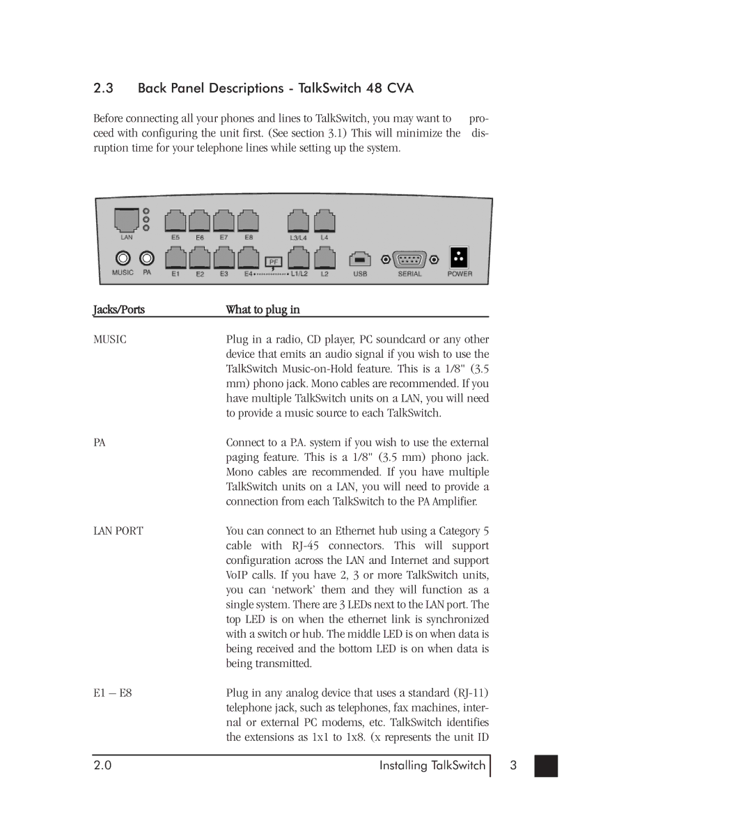
2.3Back Panel Descriptions - TalkSwitch 48 CVA
Before connecting all your phones and lines to TalkSwitch, you may want to | pro- |
ceed with configuring the unit first. (See section 3.1) This will minimize the | dis- |
ruption time for your telephone lines while setting up the system. |
|
| Jacks/Ports | What to plug in |
|
| MUSIC | Plug in a radio, CD player, PC soundcard or any other |
|
|
| device that emits an audio signal if you wish to use the |
|
|
| TalkSwitch |
|
|
| mm) phono jack. Mono cables are recommended. If you |
|
|
| have multiple TalkSwitch units on a LAN, you will need |
|
|
| to provide a music source to each TalkSwitch. |
|
| PA | Connect to a P.A. system if you wish to use the external |
|
|
| paging feature. This is a 1/8" (3.5 mm) phono jack. |
|
|
| Mono cables are recommended. If you have multiple |
|
|
| TalkSwitch units on a LAN, you will need to provide a |
|
|
| connection from each TalkSwitch to the PA Amplifier. |
|
| LAN PORT | You can connect to an Ethernet hub using a Category 5 |
|
|
| cable with |
|
|
| configuration across the LAN and Internet and support |
|
|
| VoIP calls. If you have 2, 3 or more TalkSwitch units, |
|
|
| you can ‘network’ them and they will function as a |
|
|
| single system. There are 3 LEDs next to the LAN port. The |
|
|
| top LED is on when the ethernet link is synchronized |
|
|
| with a switch or hub. The middle LED is on when data is |
|
|
| being received and the bottom LED is on when data is |
|
|
| being transmitted. |
|
| E1 – E8 | Plug in any analog device that uses a standard |
|
|
| telephone jack, such as telephones, fax machines, inter- |
|
|
| nal or external PC modems, etc. TalkSwitch identifies |
|
|
| the extensions as 1x1 to 1x8. (x represents the unit ID |
|
|
|
|
|
| 2.0 | Installing TalkSwitch | 3 |
|
|
|
|