Notes:
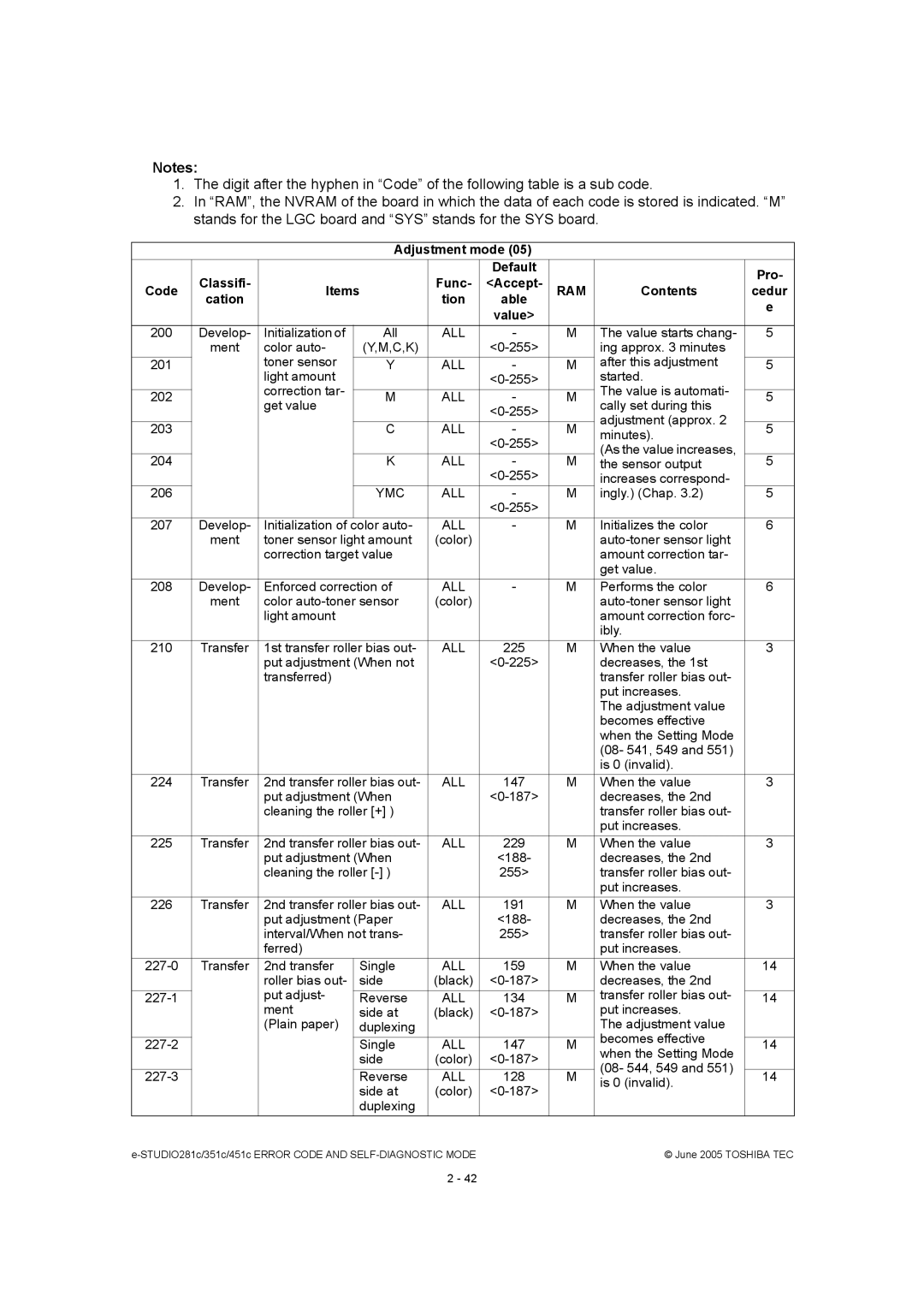
1.The digit after the hyphen in Code of the following table is a sub code.
2.In RAM, the NVRAM of the board in which the data of each code is stored is indicated. M stands for the LGC board and SYS stands for the SYS board.
|
|
|
| Adjustment mode (05) |
|
|
| ||
|
|
|
|
|
| Default |
|
| Pro- |
| Classifi- |
|
|
| Func- | <Accept- |
|
| |
Code | Items | RAM | Contents | cedur | |||||
| cation |
|
|
| tion | able |
|
| e |
|
|
|
|
|
| value> |
|
| |
|
|
|
|
|
|
|
|
| |
200 | Develop- | Initialization of | All | ALL | - | M | The value starts chang- | 5 | |
| ment | color auto- | (Y,M,C,K) |
|
| ing approx. 3 minutes |
| ||
|
| toner sensor |
|
|
|
|
| after this adjustment |
|
201 |
|
| Y | ALL | - | M | 5 | ||
|
| light amount |
|
|
| started. |
| ||
|
| correction tar- |
|
|
|
|
| The value is automati- |
|
202 |
|
| M | ALL | - | M | 5 | ||
| get value | cally set during this | |||||||
|
|
|
|
|
| ||||
|
|
|
|
|
|
| adjustment (approx. 2 |
| |
203 |
|
|
| C | ALL | - | M | 5 | |
|
|
| minutes). | ||||||
|
|
|
|
|
|
|
| ||
|
|
|
|
|
|
| (As the value increases, |
| |
204 |
|
|
| K | ALL | - | M | the sensor output | 5 |
|
|
|
|
|
|
| increases correspond- |
| |
206 |
|
|
| YMC | ALL | - | M | ingly.) (Chap. 3.2) | 5 |
|
|
|
|
|
|
|
|
| |
207 | Develop- | Initialization of | color auto- | ALL | - | M | Initializes the color | 6 | |
| ment | toner sensor light amount | (color) |
|
|
| |||
|
| correction target value |
|
|
| amount correction tar- |
| ||
|
|
|
|
|
|
|
| get value. |
|
208 | Develop- | Enforced correction of | ALL | - | M | Performs the color | 6 | ||
| ment | color | (color) |
|
|
| |||
|
| light amount |
|
|
|
| amount correction forc- |
| |
|
|
|
|
|
|
|
| ibly. |
|
210 | Transfer | 1st transfer roller bias out- | ALL | 225 | M | When the value | 3 | ||
|
| put adjustment (When not |
|
| decreases, the 1st |
| |||
|
| transferred) |
|
|
|
| transfer roller bias out- |
| |
|
|
|
|
|
|
|
| put increases. |
|
|
|
|
|
|
|
|
| The adjustment value |
|
|
|
|
|
|
|
|
| becomes effective |
|
|
|
|
|
|
|
|
| when the Setting Mode |
|
|
|
|
|
|
|
|
| (08- 541, 549 and 551) |
|
|
|
|
|
|
|
|
| is 0 (invalid). |
|
224 | Transfer | 2nd transfer roller bias out- | ALL | 147 | M | When the value | 3 | ||
|
| put adjustment (When |
|
| decreases, the 2nd |
| |||
|
| cleaning the roller [+] ) |
|
|
| transfer roller bias out- |
| ||
|
|
|
|
|
|
|
| put increases. |
|
225 | Transfer | 2nd transfer roller bias out- | ALL | 229 | M | When the value | 3 | ||
|
| put adjustment (When |
| <188- |
| decreases, the 2nd |
| ||
|
| cleaning the roller |
| 255> |
| transfer roller bias out- |
| ||
|
|
|
|
|
|
|
| put increases. |
|
226 | Transfer | 2nd transfer roller bias out- | ALL | 191 | M | When the value | 3 | ||
|
| put adjustment (Paper |
| <188- |
| decreases, the 2nd |
| ||
|
| interval/When not trans- |
| 255> |
| transfer roller bias out- |
| ||
|
| ferred) |
|
|
|
| put increases. |
| |
Transfer | 2nd transfer | Single | ALL | 159 | M | When the value | 14 | ||
|
| roller bias out- | side | (black) |
| decreases, the 2nd |
| ||
|
| put adjust- |
|
|
|
|
| transfer roller bias out- |
|
|
| Reverse | ALL | 134 | M | 14 | |||
|
| ment | side at | (black) |
| put increases. |
| ||
|
| (Plain paper) | duplexing |
|
|
| The adjustment value |
| |
|
|
|
|
|
|
|
| becomes effective |
|
|
|
| Single | ALL | 147 | M | 14 | ||
|
|
| when the Setting Mode | ||||||
|
|
|
| side | (color) |
|
| ||
|
|
|
|
| (08- 544, 549 and 551) |
| |||
|
|
| Reverse | ALL | 128 | M | 14 | ||
|
|
| is 0 (invalid). | ||||||
|
|
|
| side at | (color) |
|
| ||
|
|
|
|
|
|
| |||
|
|
|
| duplexing |
|
|
|
|
|
|
| © June 2005 TOSHIBA TEC | |||||||
2 - 42