Installing the Control and RF Receiver Circuit Boards Together in the Cabinet
1.Hang two short (black) mounting clips (provided with receiver) on the raised cabinet tabs, as shown in Detail B in Figure 3.
2.Insert the top of the receiver board (removed from its own case as de- scribed in its instructions) into the slots at the top of the cabinet, as shown in Detail A in Figure 3. Make sure that the board rests on the correct row of tabs, as shown.
3.Swing the base of the board into the mounting clips and secure it to the cabinet with the accompanying screws (see Detail B in Fig. 3).
4.Insert the top of the control's board into the slot in the clips and position two long (red) clips at the lower edge of the board (see Detail C).
5.Swing this board into place and secure it with two additional screws.
6.Insert grounding lugs (supplied with the receiver) through the top of the cabinet into the
7.Insert the receiver's antennas through the top of the cabinet, into the
8.Setup and wiring of the receiver. is contained in the WIRELESS (RF) ZONE EXPANSION (5700 & 5800 RF SYSTEMS) section.
Standard Phone Line Connections
The wiring connections shown here are not applicable if the 4285 Phone module is used. Refer to the 4285 Phone module section for information regarding phone line connections, which are different than those shown here.
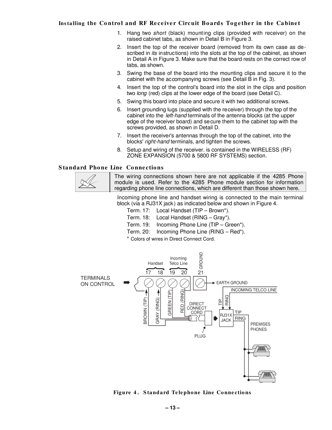
Incoming phone line and handset wiring is connected to the main terminal block (via a RJ31X jack) as indicated below and shown in Figure 4.
Term. 17: Local Handset (TIP – Brown*).
Term. 18: Local Handset (RING – Gray*).
Term. 19: Incoming Phone Line (TIP – Green*).
Term. 20: Incoming Phone Line (RING – Red*).
*Colors of wires in Direct Connect Cord.
TERMINALS | ➡ |
ON CONTROL |
{ { | GROUND | |||
|
| Incoming |
| |
Handset | Telco Line |
| ||
17 | 18 | 19 | 20 | 21 |
▲ EARTH GROUND
BROWN (TIP)
GRAY (RING)
GREEN (TIP)
RED (RING)
DIRECT
CONNECT
CORD
PLUG
|
|
|
| INCOMING TELCO LINE | ||||||||||||||
TIP |
| RING |
|
|
|
|
|
|
|
|
|
|
|
|
|
|
| |
|
|
|
|
|
|
|
|
|
|
|
|
|
|
|
|
|
|
|
| ▲ |
|
|
|
|
|
|
|
|
|
|
|
|
|
|
|
| |
| ▲ | TIP | ||||||||||||||||
| RJ31XJACK | |||||||||||||||||
➧ | RING |
|
|
|
|
|
|
|
|
|
|
|
| |||||
|
| PREMISES | ||||||||||||||||
|
|
|
|
|
|
| ||||||||||||
|
|
|
|
|
|
| PHONES | |||||||||||
|
|
|
|
|
|
|
|
|
|
|
|
|
|
|
|
|
|
|
|
|
|
|
|
|
|
|
|
|
|
|
|
|
|
|
|
|
|
|
|
|
|
|
|
|
|
|
|
|
|
|
|
|
|
|
|
|
|
|
|
|
|
|
|
|
|
|
|
|
|
|
|
|
|
|
|
|
|
|
|
|
|
|
|
|
|
|
|
|
|
|
|
|
|
|
|
|
|
|
|
|
|
|
|
|
|
|
|
|
|
|
|
|
|
|
|
|
|
|
|
|
|
|
|
|
|
|
|
|
|
|
|
|
|
|
|
|
|
|
|
|
|
|
|
|
|
|
|
|
|
|
|
|
|
|
|
|
|
|
|
|
|
|
|
|
|
|
|
|
|
|
Figure 4. Standard Telephone Line Connections
– 13 –