1.Make 12V (+) and
Color Lead | Terminal On Control * |
GREEN | DATA IN (terminal 6) |
BLACK | AUX – (terminal 4) |
RED | AUX + (terminal 5) |
YELLOW | DATA OUT (terminal 7) |
|
|
*These are the same connections as those used for remote keypads .
2.Insert the keyed connector at the other end of the connector cable into the mating header on the Phone module (see diagram on next page for location of the header).
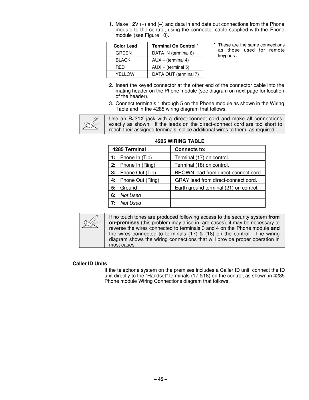
3.Connect terminals 1 through 5 on the Phone module as shown in the Wiring Table and in the 4285 wiring diagram that follows.
Use an RJ31X jack with a
4285 WIRING TABLE
4285 Terminal | Connects to: | |
1: | Phone In (Tip) | Terminal (17) on control. |
2: | Phone In (Ring) | Terminal (18) on control. |
3: | Phone Out (Tip) | BROWN lead from |
4: | Phone Out (Ring) | GRAY lead from |
5: | Ground | Earth ground terminal (21) on control. |
6: | Not Used |
|
7: | Not Used |
|
|
|
|
If no touch tones are produced following access to the security system from
Caller ID Units
If the telephone system on the premises includes a Caller ID unit, connect the ID unit directly to the “Handset” terminals (17 &18) on the control, as shown in 4285 Phone module Wiring Connections diagram that follows.
– 45 –
