Data field ✱22 RF SYSTEM TYPE, must have been programmed for a 5700 RF system (“1”). Also, the House ID should have been entered in field✱24, and all 5700 transmitters set to the same House ID.
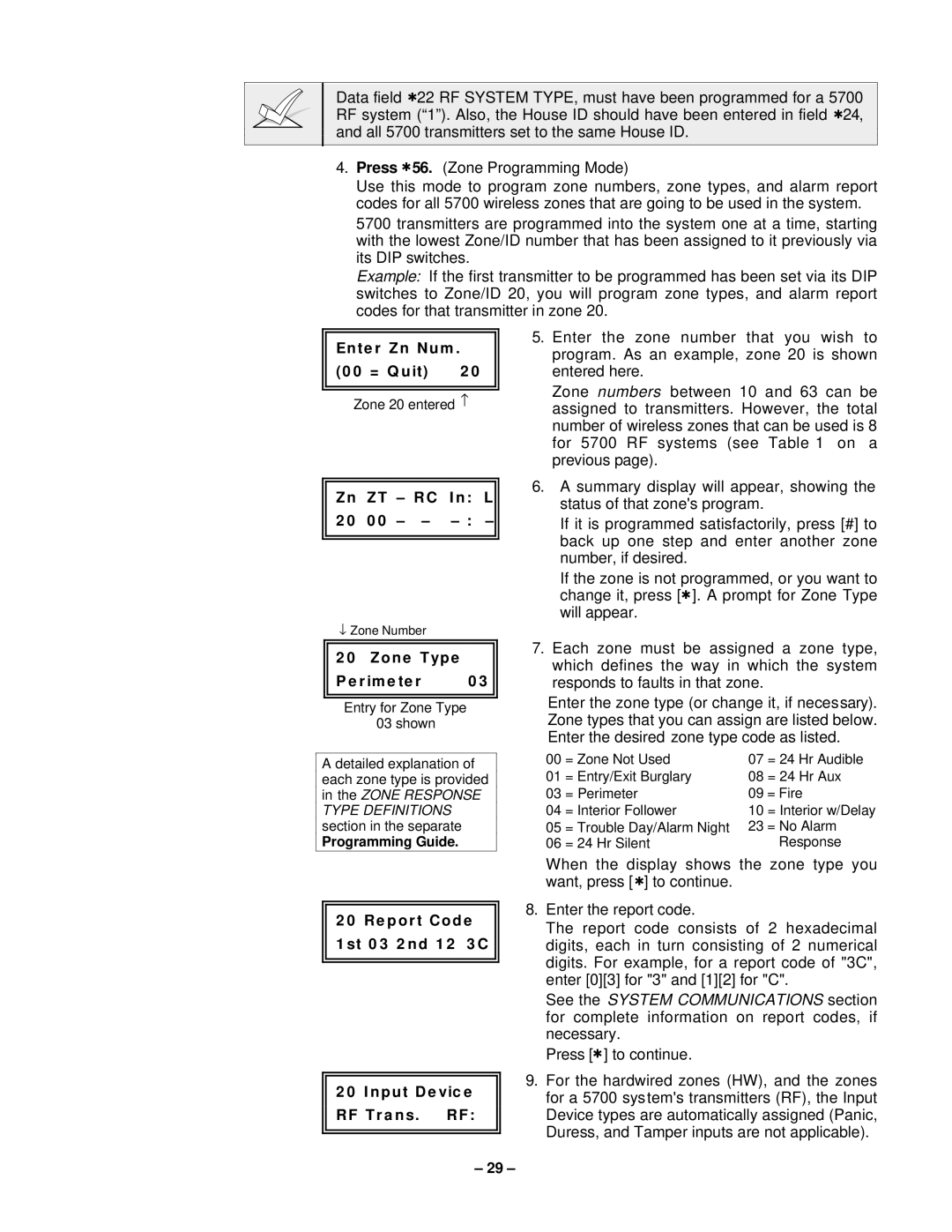
4.Press ✱56. (Zone Programming Mode)
Use this mode to program zone numbers, zone types, and alarm report codes for all 5700 wireless zones that are going to be used in the system.
5700 transmitters are programmed into the system one at a time, starting with the lowest Zone/ID number that has been assigned to it previously via its DIP switches.
Example: If the first transmitter to be programmed has been set via its DIP switches to Zone/ID 20, you will program zone types, and alarm report codes for that transmitter in zone 20.
Ente r Zn Num .
(0 0 = Q uit) | 2 0 |
Zone 20 entered ↑
|
|
|
|
|
|
|
|
| Zn | ZT | – | RC | In: | L |
|
| 2 0 | 0 0 | – | – | – |
| |
|
|
|
|
|
|
|
|
|
|
|
|
|
|
|
|
↓Zone Number
5.Enter the zone number that you wish to program. As an example, zone 20 is shown entered here.
Zone numbers between 10 and 63 can be assigned to transmitters. However, the total number of wireless zones that can be used is 8 for 5700 RF systems (see Table 1 on a previous page).
6.A summary display will appear, showing the status of that zone's program.
If it is programmed satisfactorily, press [#] to back up one step and enter another zone number, if desired.
If the zone is not programmed, or you want to change it, press [✱]. A prompt for Zone Type will appear.
2 0 Zone Type
Pe r ime te r | 0 3 |
Entry for Zone Type
03 shown
A detailed explanation of each zone type is provided in the ZONE RESPONSE TYPE DEFINITIONS section in the separate
Programming Guide.
7.Each zone must be assigned a zone type, which defines the way in which the system responds to faults in that zone.
Enter the zone type (or change it, if necessary). Zone types that you can assign are listed below. Enter the desired zone type code as listed.
00 | = Zone Not Used | 07 | = 24 Hr Audible |
01 | = Entry/Exit Burglary | 08 | = 24 Hr Aux |
03 | = Perimeter | 09 = Fire | |
04 | = Interior Follower | 10 | = Interior w/Delay |
05 | = Trouble Day/Alarm Night | 23 | = No Alarm |
06 | = 24 Hr Silent |
| Response |
2 0 Re por t Code
1 st 0 3 2 nd 1 2 3 C
2 0 Input De vic e RF Tr a ns. RF:
When the display shows the zone type you want, press [ ✱] to continue.
8.Enter the report code.
The report code consists of 2 hexadecimal digits, each in turn consisting of 2 numerical digits. For example, for a report code of "3C", enter [0][3] for "3" and [1][2] for "C".
See the SYSTEM COMMUNICATIONS section for complete information on report codes, if necessary.
Press [✱] to continue.
9.For the hardwired zones (HW), and the zones for a 5700 system's transmitters (RF), the Input Device types are automatically assigned (Panic, Duress, and Tamper inputs are not applicable).
– 29 –
